60
PKG-SVX027D-EN
Unit Setup
Table 19. Unit setup setpoints that can be modified in the TD-7
Setpoint Name
Description
Factory
Default
Condenser Control % of Design
Percent of the condenser pressure design the unit will control to and is user adjustable between
50-100%.
90%
Condenser Tee Strainer Sensor Calibration
The condenser water tee high and low pressure sensor can be calibrated to match the gauge
readings or recorded readings by the balancer.
0
Condenser Purge Status
(On Units with Condenser Valves Only)
Each compressor has its own condenser purge status value which indicates when the
condenser valve is open in the purge mode. It can also be used to manually initiate the purge
mode for each compressor.
Off
Condenser Water Flow Type
(On Units with Condenser Valves Only)
Indicates if the unit is a constant or variable volume flow type unit. Even with the condenser
water regulating valves installed on each compressor, the flow type can be changed. When the
flow is changed from variable flow to constant flow, the water regulating valve will open to its
maximum position when the unit is occupied. This can be done for constant volume flow
systems that do not include a VFD Pump.
Variable flow
Water Side Economizer Lockout BAS
(Units with Water Side Economizer Only)
The water side economizer can be locked out by the controls system.
Available
Compressor Lockout BAS Each compressor can be locked out individually by the controls system.
Available
Fan Lockout BAS
Each fan can be locked out individually by the controls system. Fans should be made available
prior to startup.
Available
To modify any of the setpoints in the table above:
1. Press Reports at the bottom of the screen.
2. Press the Unit Setup button.
3. On the Setup report, locate the point in the menu. Use
the arrows to scroll through the report if needed.
4. Use the up and down arrows to change the value, or
press inside the box and type in the desired setpoint.
5. Press Save.
Reports
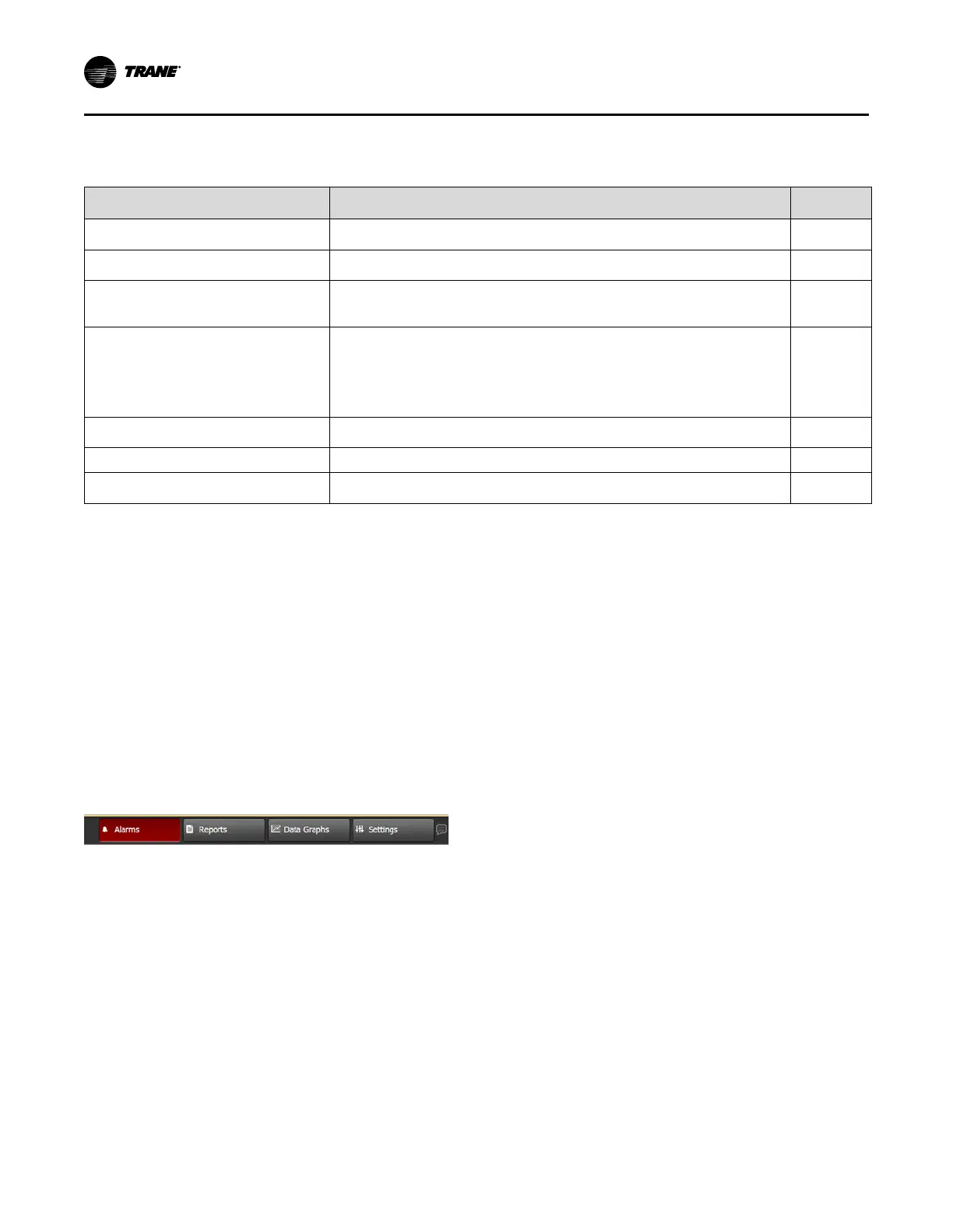
To access Alarms, press the Alarms button in the lower left
corner of the screen. If the Alarm tab is not blinking red,
there are no alarms present.
Figure 48. Alarms tab
Compressor Alarms
If there is a compressor alarm, it will need to be manually
reset after it is resolved. Each compressor needs to be
reset manually:
1. Press Reports at the bottom of the display.
2. Press Unit Setup.
3. In the Setup report, locate the appropriate point. Use
the arrows to scroll through the report if needed.
4. Select the specific compressor.
5. Change the value from Normal to Reset.
6. Press Save. The point will automatically revert to its
default setting (Off).
Fan Alarms
If there is a fan alarm, it will need to be manually reset after
it is resolved. There is one fan reset for the entire wall fan.
1. Press Reports at the bottom of the display.
2. Press Unit Setup.
3. In the Setup report, press Supply Fan Failure Reset.
Use the arrows to scroll through the report if needed.
4. Press Reset.
5. Press Save.
6. When you want the fan to be available, press the
Release Override button in the top left.
General Alarms
General alarms are alarms that are not tied to fans or
compressors. They require a manual reset, and there is
one alarm reset for these alarms.
To reset a general alarm:
1. Press Reports at the bottom of the display.
2. Press Unit Setup.
3. In the Setup report, press Alarm Reset. Use the
arrows to scroll through the report if needed.
4. Press Reset.
5. Press Save.
Controls
 Loading...
