PKG-SVX027D-EN
57
Table 17. Points list (continued)
Hardware Connection Point Name
Point Setup
XM32.13
BO1
Dirty Filter Alarm NO Open = Normal, NO Closed = Alarm; NC Not used
BO2
Refrigeration Circuit Failure Alarm Open = Normal, Closed = Alarm
BO3
Supply Fan Failure Alarm Open = Normal, Closed = Alarm
BO4 Heat Failure Alarm
Open = Normal, Closed = Alarm
XM30.14
AO1/UI1
Occupied Zone Cool Setpoint
0.5 Vdc = 50°F, 4.5 Vdc = 90°F
AO2/UI2
Occupied Zone Heat Setpoint
0.5 Vdc = 50°F, 4.5 Vdc = 90°F
AO3/UI3
Unoccupied Zone Cool Setpoint
0.5 Vdc = 50°F, 4.5 Vdc = 90°F
AO4/UI4
Unoccupied Zone Heat Setpoint
0.5 Vdc = 50°F, 4.5 Vdc = 90°F
XM30.15
AO1/UI1
Supply Air Cooling Setpoint
0.5 Vdc = 40°F, 4.5 Vdc = 90°F
AO2/UI2
Supply Air Heating Setpoint
0.5 Vdc = 40°F, 4.5 Vdc = 90°F
AO3/UI3
Supply Air Static Pressure Setpoint
0.5 Vdc = 0 In WC, 4.5 Vdc = 5 In WC
AO4/UI4
Demand Limit Input
Open = Normal, Closed = 50% Reduction
NO = Normally Open, NC = Normally Closed
Navigating the TD-7
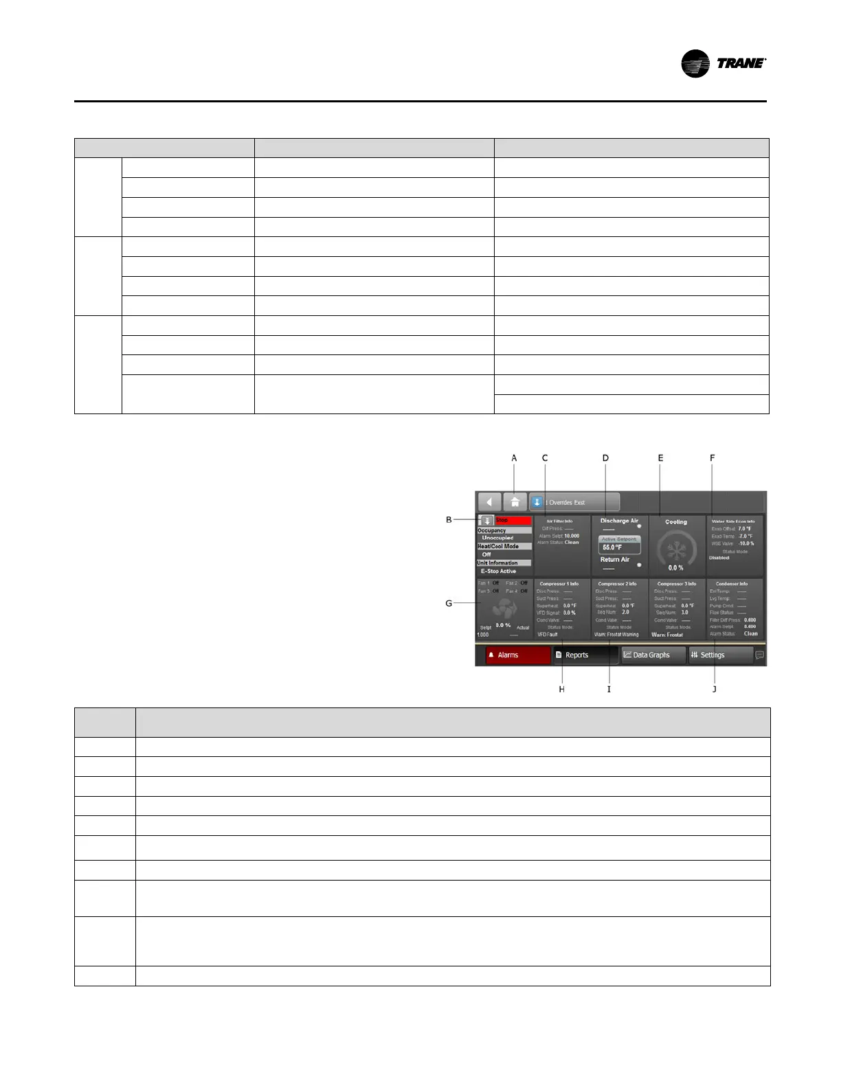
TD-7 Home Screen
To access the TD-7 home screen, press the Home button
in the upper left of the screen.
Figure 43. Home screen
Screen
Element
Description
A Home button
B
Displays the local Auto Stop button and displays the occupancy, Heat/Cool Mode, and Unit Information.
C
Displays information about the Air Filter.
D
Displays the Discharge Air Temperature, Setpoint, and Return Air Temperature. A red light displays if the sensor fails.
E
Displays when cooling is active and indicates the % of cooling capacity currently utilized.
F
The Water Side Econ Info tile is included on units with an economizer installed.
Displays a snapshot of economizer operations and the mode of the economizer.
G
Displays fan status (on, off), duct static pressure setpoint and actual, and fan percentage.
H
Compressor 1 is always the lead compressor.
This tile displays the compressor pressures, superheat, VFD signal, condenser water values (if included), and operating mode.
I
Tiles for compressors 2-4 display, depending on the number of compressors installed.
The VFD compressor is always the lead compressor. The fixed speed compressors rotate to even out run time.
Compressor tiles displays the compressor pressures, superheat, VFD signal, condenser water values (if included), and operating mode.
J
Displays the entering and leaving temperatures, pump command, flow status, and the condenser alarm status.
Controls
 Loading...
