42
PKG-SVX027D-EN
a. Verify:
• No continuity between phases.
• No continuity between each phase and ground.
b. Do not hi-pot with variable speed compressor
drives or fan fuses installed or fixed speed
compressor motor protection module connected.
3. Once all these items above have been verified:
a. Replace control power transformer primary fuse.
4. Connect main power and ground.
5. With fixed speed compressor circuit breakers, and fan
fuse holders open, and variable speed compressor
enable plug removed, apply power to unit using the unit
or remote mounted disconnect switch.
Important: With a phase rotation meter, verify
clockwise rotation at the terminal block
using standard electrical safety
procedures.
6. After clockwise rotation is confirmed, remove main
power unit and verify the unit is de-energized.
7. With fixed speed compressor circuit breakers still open,
and variable speed compressor enable plug still
removed, close fan fuse holders and re-apply power.
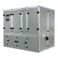
TD-7 Installation
1. Hold faceplate on front side of Low Voltage door and
install TD-7 onto front of Low Voltage door.
Figure 35. TD-7 Face plate
Figure 36. TD-7 Installation on front
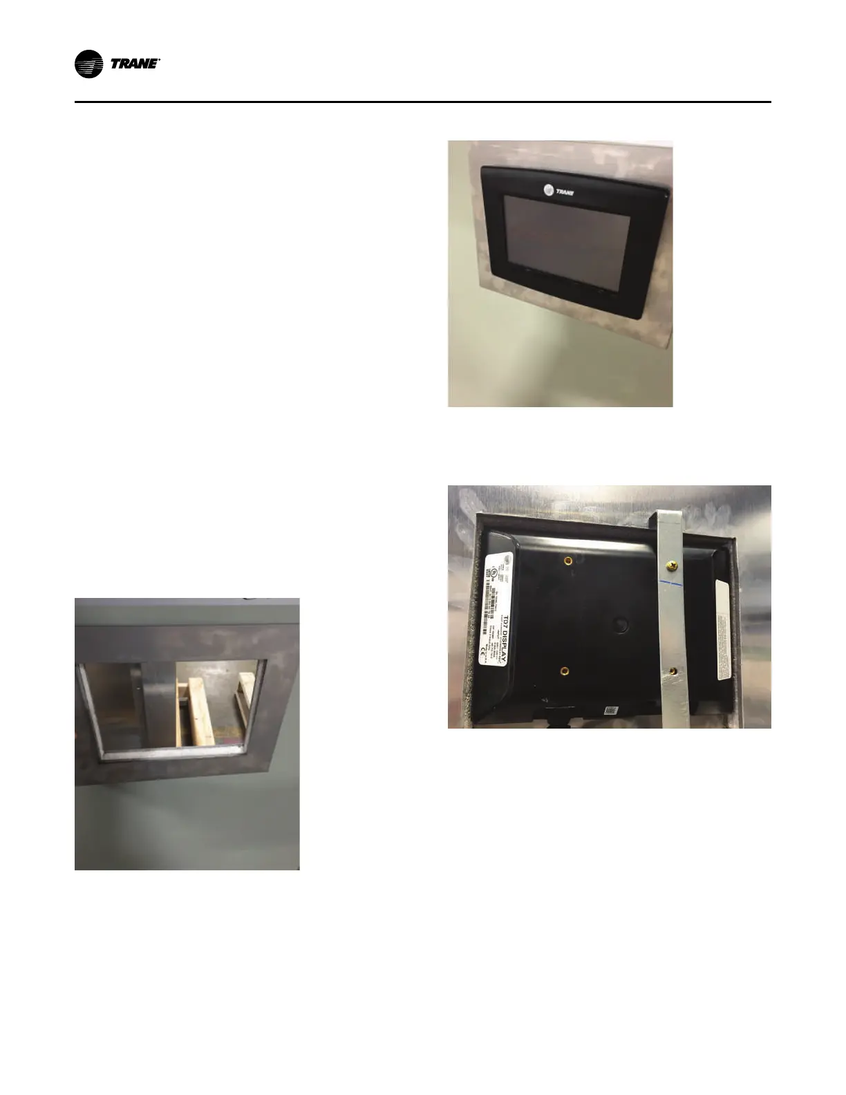
2. Attach brackets on back side of Low Voltage door to
secure the TD-7 to the door.
Figure 37. TD-7 Installation on back with brackets
Installation - Mechanical
 Loading...
