PKG-SVX027D-EN
45
Table 15. Electrical service sizing data — motors (continued)
Tonnage
Model Number
Unit Wiring
Motor Data
Compressor (EA) Fan (EA)
Fixed Speed Variable Speed
VSD
Nameplate
Voltage
Voltage
Range
MCA MOP Disc
Qty
RLA LRA
Qty
Max
Input (A)
Qty
kW FLA
80
SCWMN08LF Low MCA 208-230/60/3 187-253 335.3 400 375 3 55.77 340 1 56 5 6.15 18.6
SCWMN080F 208-230/60/3 187-253 370.3 450 400 3 55.77 340 1 84 5 6.15 18.6
SCWMN08L4 Low MCA 460/60/3 414-506 156.2 175 175 3 23.72 110 1 30 5 6.15 9
SCWMN0804 460/60/3 414-506 193.7 250 200 3 23.72 110 1 60 5 6.15 9
Notes:
1. MCA: Minimum Circuit Ampacity is 125% of the largest compressor RLA or Drive input current, plus 100% of the other compressor (s) RLA, plus the sum of the
condenser fan RLA, plus any other load rated at 1 AMP or more.
2. Maximum Breaker Overcurrent Protection (MOP): 225% of the largest compressor RLA or VSD drive Input, plus 100% of the other compressor(s) RLA, plus the sum of
the condenser fan Motor/Drive FLA, plus any other load rated at 1 AMP or more.
3. Recommended disconnect switch: 110% to 115% of the sum of the RLA of the compressors, VSD drive input, fan motor/drive and controls FLA.
4. RLA: Rated in accordance with UL standard 1995
5. Local codes may take precedence.
6. Fix speed compressor are across the line starting, the VSD compressors are controlled by VSD drive. Compressors will never start simultaneously.
7. Voltage utilization range is ±10 percent.
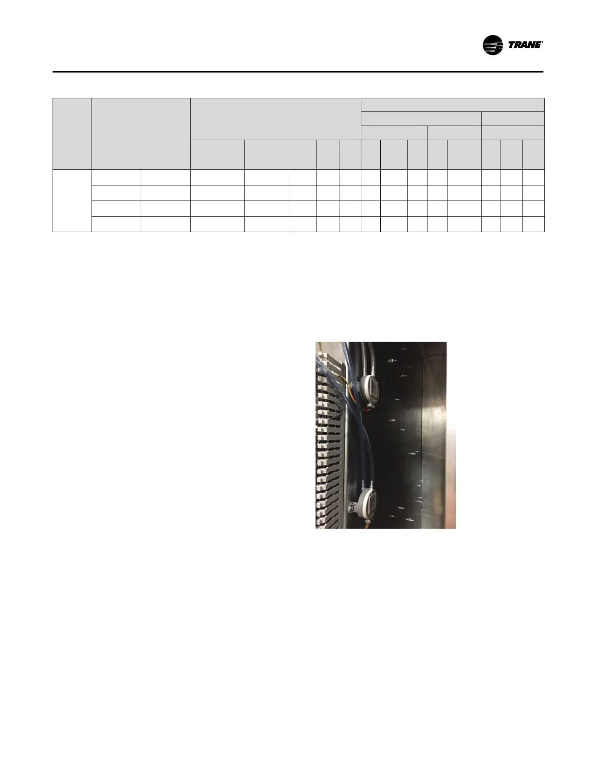
Static Pressure Sensor
Installation (VAV units only)
Supply air static pressure controls the inverter option. A
bulkhead fitting and a roll of vinyl tubing is provided for
direct insertion into ductwork. If a specific head assembly
or remote location is desired, then this material will be the
responsibility of the installer. There are two pressure
transducers mounted on the side of the control panel. The
top is the static pressure transducer and the bottom is the
filter differential transducer.
Sensor Location
1. Install static pressure sensor in specified location or
section of ductwork most critical to the VAV operation.
2. If installation location is remote to transducer in control
panel, do not exceed 250 feet for ¼-inch OD tubing or
500 feet for 3/8-inch OD tubing.
Installing the Tubing Sensor
1. Unscrew the ¼-inch bulkhead fitting provided.
2. Drill ½-inch hole in ductwork at desired location.
3. Insert external end of bulkhead fitting through the hole
from inside the duct.
4. Insert ¼-inch tubing through both halves of union
bulkhead fitting into ductwork.
5. Screw internal end and tighten onto ductwork.
6. Run the opposite end of tubing through hole in the top
of the control panel cabinet.
7. Connect to the push-on connection at the top pressure
transducer in the control panel.
Figure 38. Static pressure tube
Note: If plastic tubing pulls away from a connection, trim it
back before replacing it on the fitting. Stretched
tubing may leak and cause faulty control.
Installation - Electrical
 Loading...
