PKG-SVX027D-EN
51
It will annunciate either High Pressure Cutout Compressor
X or Compressor Safety Circuit X.
Variable Speed Compressor (VS)
The VS compressor does not have an external crankcase
heater (like FS compressors). Instead, whenever the VS
compressor is off, the VS drive applies a voltage to the
compressor motor stator such that the compressor doesn't
rotate but heats the oil.
The VS drive, 1U1, has its own software to control and
protect the VS compressor. See Figure 41, p. 52 for VSD
Input/Output terminals.
The drive receives the following signals from the Unit
Controller:
• Controlled Start/Stop
• Speed signal
• Drive Reset
• Stator Heat Enable
• Emergency stop
Note: The 24 Vdc voltage used in each of the circuits
above -except the speed signal-originate from the
VS drive.
The drive provides the following signals to the Unit
Controller:
• Compressor On status
• Drive Fault status
Upon a call for mechanical cooling, the Unit Controller
issues the command to start the compressor via a dry
contact closure on XM32.3. When the 1U1 drive receives a
Controlled Start signal it runs the compressor at 3600 rpm
for 60 seconds. The compressor then runs at whatever
speed commanded by the Unit Controller. Similarly, when
the 1U1 drive receives a Controlled Stop signal it runs the
compressor at 3600 rpm for 60 seconds then turns the
compressor off.
The VS compressor HPC is wired in series with the 1U1 E-
stop circuit. A VS compressor HPC event or upon a Unit
Controller remote Emergency Stop input will immediately
stop the VS compressor and lockout its operation on a
manually resettable diagnostic.
Compressor Limit Conditions
Because the MSC uses suction and discharge pressure
sensors rather than limit switches, the Unit Controller can
sense when a refrigerant circuit is approaching a high or
low pressure limit condition.
Low Pressure Limit conditions can be caused by the
following:
• Low discharge air temperature
• Low airflow
• Dirty air filters
• TXV malfunction
• Low refrigerant charge
• Faulty suction pressure sensor
High Pressure Limit conditions can be caused by the
following:
• Low condenser water flow
• High entering condenser water temperature
• Fouled entering condenser water strainer
• TXV malfunction
• Refrigerant over charge
• Water regulating valve (WRV) malfunction
• Faulty discharge pressure sensor
The Unit Controller's TD7 will annunciate a Limit Condition
if an FS compressor circuit enters one. If the unit is
equipped with WRV, the Unit Controller can open the valve
to allow more flow through the condenser to help mitigate
HPC trip.
If the VS circuit enters either a High or Low Pressure limit
condition the Unit Controller can reduce compressor speed
to help mitigate either a Low or High pressure diagnostic
trip.
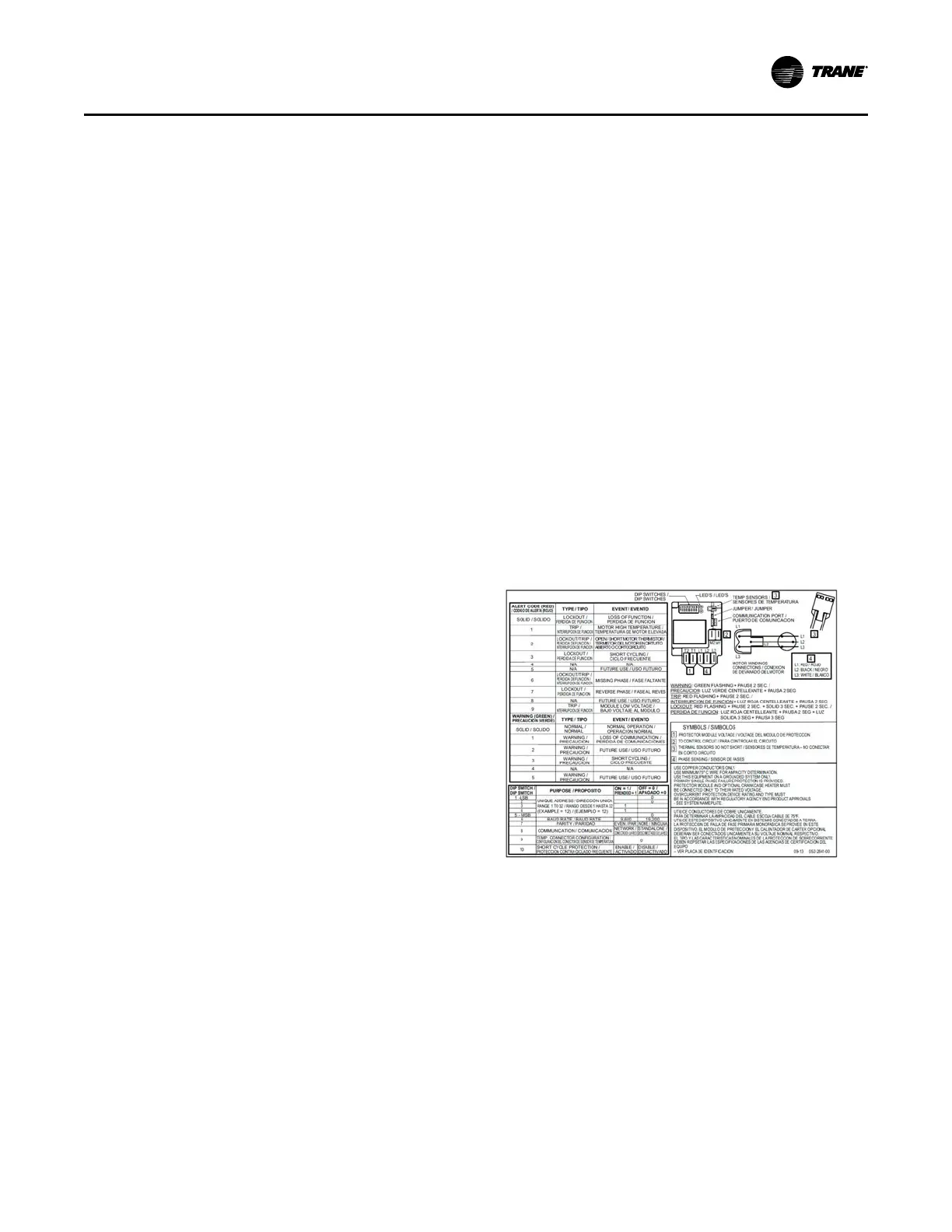
Figure 40. Fixed speed compressor protection
module (MCSP)
Operating Principles
 Loading...
