Encompass 4 Reader System Guide
TransCore Proprietary.
4-38
• Any terminal emulation program running on a PC
• Communications cable to connect to the COM1 port on your PC
Encompass 4 Reader communications and customer interface signals are supplied from the Encompass
4 Reader to the host through a multi-wire cable, which is a 13-pair pigtail. The connector for this cable is
located on the back of the Encompass 4 Reader. Refer to the following sections to connect the appropriate
communications wires from the cable to the PC.
These sections contain instructions for connecting RS–232 and RS–422 communications between the
Encompass 4 Reader and the PC for bench testing purposes. Each section contains wiring instructions and
pin assignments followed by step-by-step connection procedures.
The Encompass 4 Reader can remain powered up while connecting reader-to-host PC communications.
Connecting for Bench Testing with RS–232 Interface
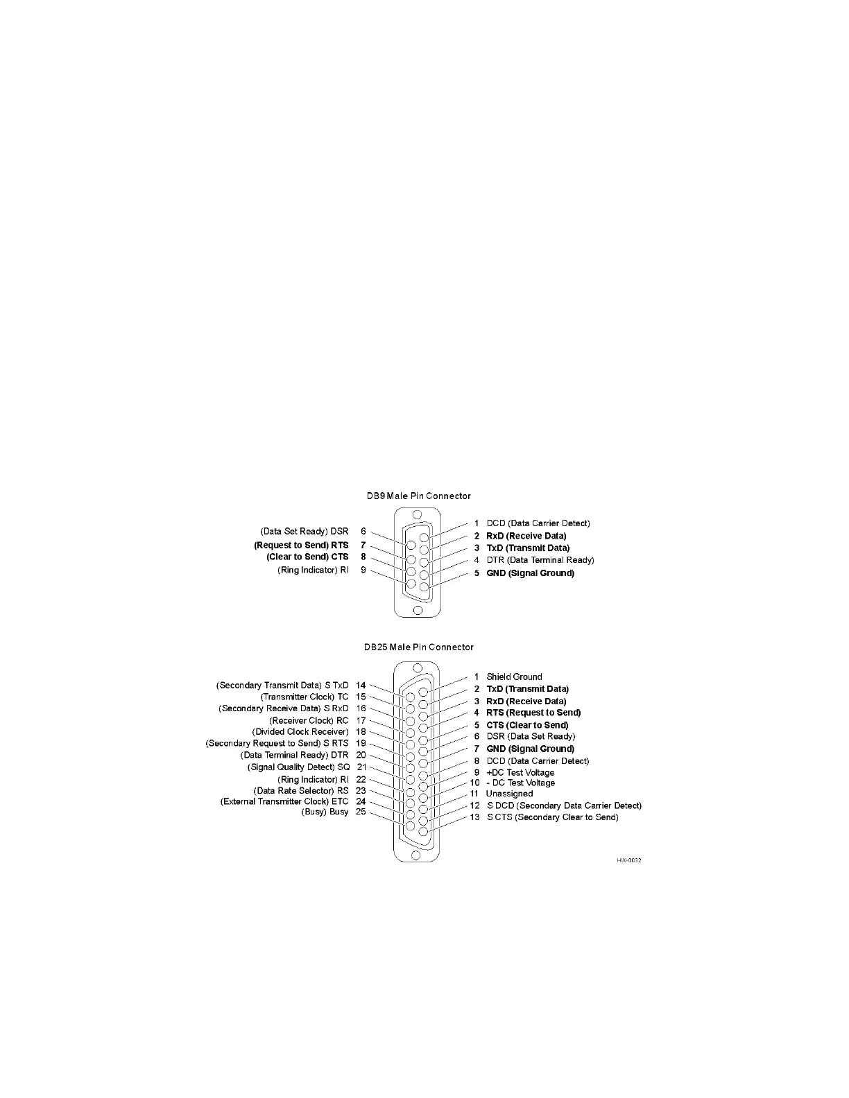
RS–232 interface signals are supplied by three or five wires from the Encompass 4 communications cable.
The pin assignments for the signal to the host male DB9 and DB25 connectors are shown in boldface in
Figure 28.
Note: Supported pin assignments are in boldface.
Figure 28 Pin Assignments for Signal to Host Connectors

 Loading...
