Chapter 4 Installing the Encompass 4 Reader
TransCore Proprietary
4-57
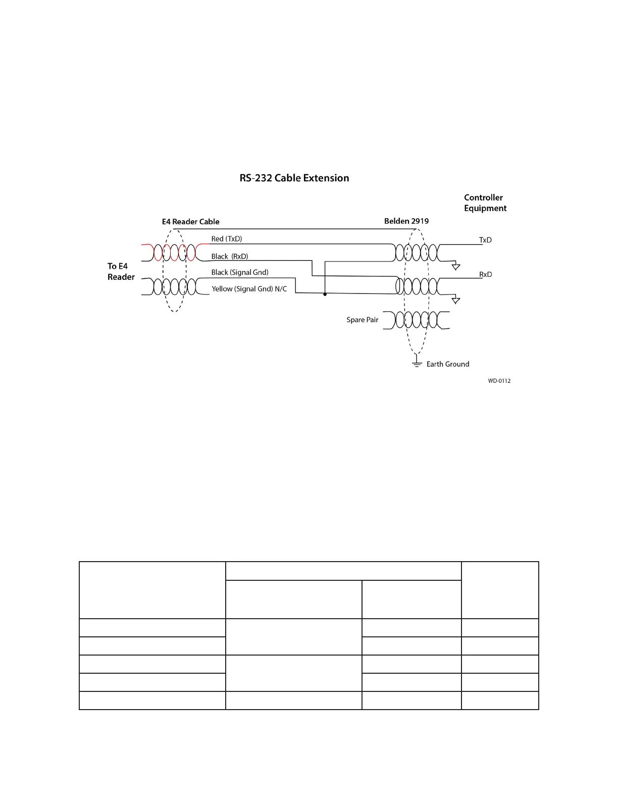
Note: When extending the RS-232 interface, use a three-pair cable such as Belden 2919. Use a
twisted pair for the Black (RxD) with ground (Black of the Black and Yellow pair), and a twisted pair
for Red (TxD) with ground (Black of the Black and Yellow pair). The third pair of the three-pair cable
can be used for a spare in the event either of the other two pair are damaged or fail. The cable
shield should be tied to a single-point Earth Ground on the controller end of the cable Refer to
Figure 45.
RS–422 Interface
RS–422 interface signals are supplied by four wires from the Encompass 4 Reader communications cable.
Your host must have an RS–422 interface with either an internal or external converter.
Table 12 shows the RS–422 signals and their interface wires. To see the alternate wire (15-pair)
assignments, refer to “Table 49 RS–422 Interface Signal Wiring for Alternate Wire 15-Pair Cable” on
page C–2.
Table 12 RS–422 Interface Signal Wiring for Colored-Wire 13-Pair Cable
Signal from Encompass 4
Reader
Colored-Wire Pair Cable
Connect to
DB9 Pin
Wire Pair from
Encompass 4 Reader
Color Used
RS–422 Transmit positive
Yellow/Red
Yellow Pin 7
RS–422 Transmit negative Red Pin 8
RS–422 Receive positive
Red/Black
Black Pin 2
RS–422 Receive negative Red Pin 3
Signal Ground Yellow/Black Yellow or Black Pin 5
Figure 45 RS-232 Cable Extension Diagram

 Loading...
