Chapter 4 Installing the Encompass 4 Reader
TransCore Proprietary
4-63
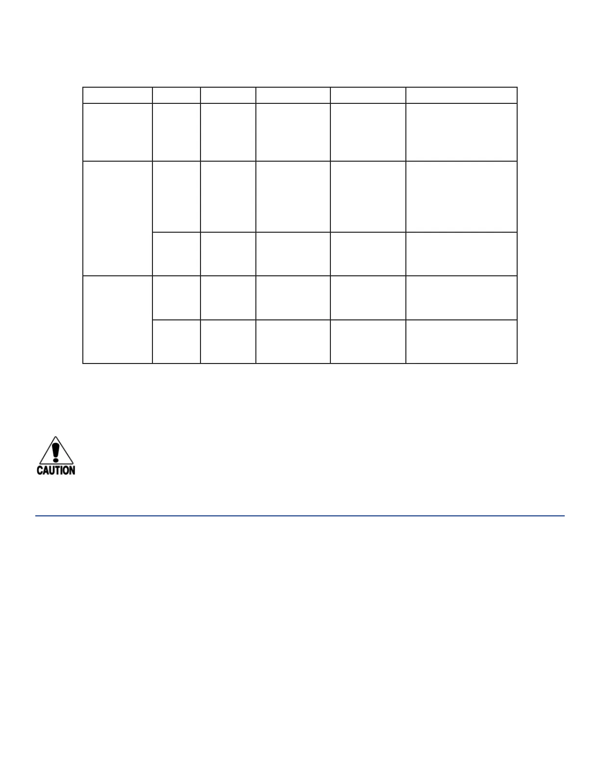
Table 14 Sense Input/Output Cabling 13-Pair Assignments
Pair Pin Color Signal Description Typical Function
White/
Black
Z Black
Sense
Output1_
COM
Sense
Output1,
common
terminal
Switched sense
output
White/
Black
Z
a
Black Sync_485_P
RS–485 bus
positive
Used to connect
Encompass 4
Readers with IAG
capability on a
synchronization bus
a White
Sense
Output1_NC
Sense
Output1 NC
terminal
Switched sense
output
Yellow/
Black
b Yellow GND Logic ground
Signal ground used
with RS–232 and
Wiegand
c Black GND Logic ground
Signal ground used
with RS–232 and
Wiegand
a Use this synchronization pin designation if installing an Encompass 4 Reader that reads IAG protocol tags. The part
numbers for these readers are as follows:
10-4002-004; 10-4002-010; 10-4002-019; 10-4004-004; 10-4004-010; 10-4004-019; 10-4012-004; 10-4012-010; 10-4012-019;
10-4014-004; 10-4014-010; 10-4014-019
Caution
After connecting the wires in the communications cable, ground all drain wires from the
communications cable to the chassis ground in the NEMA enclosure.
Marking the Read Zone
The area where the Encompass 4 reads tags at the current RF range is called the read zone. The antenna
pattern, or read zone, of the Encompass 4 Reader would look roughly like a pear-shaped balloon if you
were able to see it. When installing the Encompass 4 Reader, you should first mark the unit’s read zone
using the RF range set at the factory-default maximum. You can later adjust the read zone using the
techniques discussed in “Fine-Tuning and Verifying the Read Zone” on page 8–146.
If two Encompass 4 Readers are installed near each other, TransCore recommends that you fine-tune
each reader for the ideal read zone before connecting it permanently to sense input/sense output and
communications cables. A minimum of 2 MHz frequency separation between the two adjacent readers is
required for correct operation.
 Loading...

