-23-
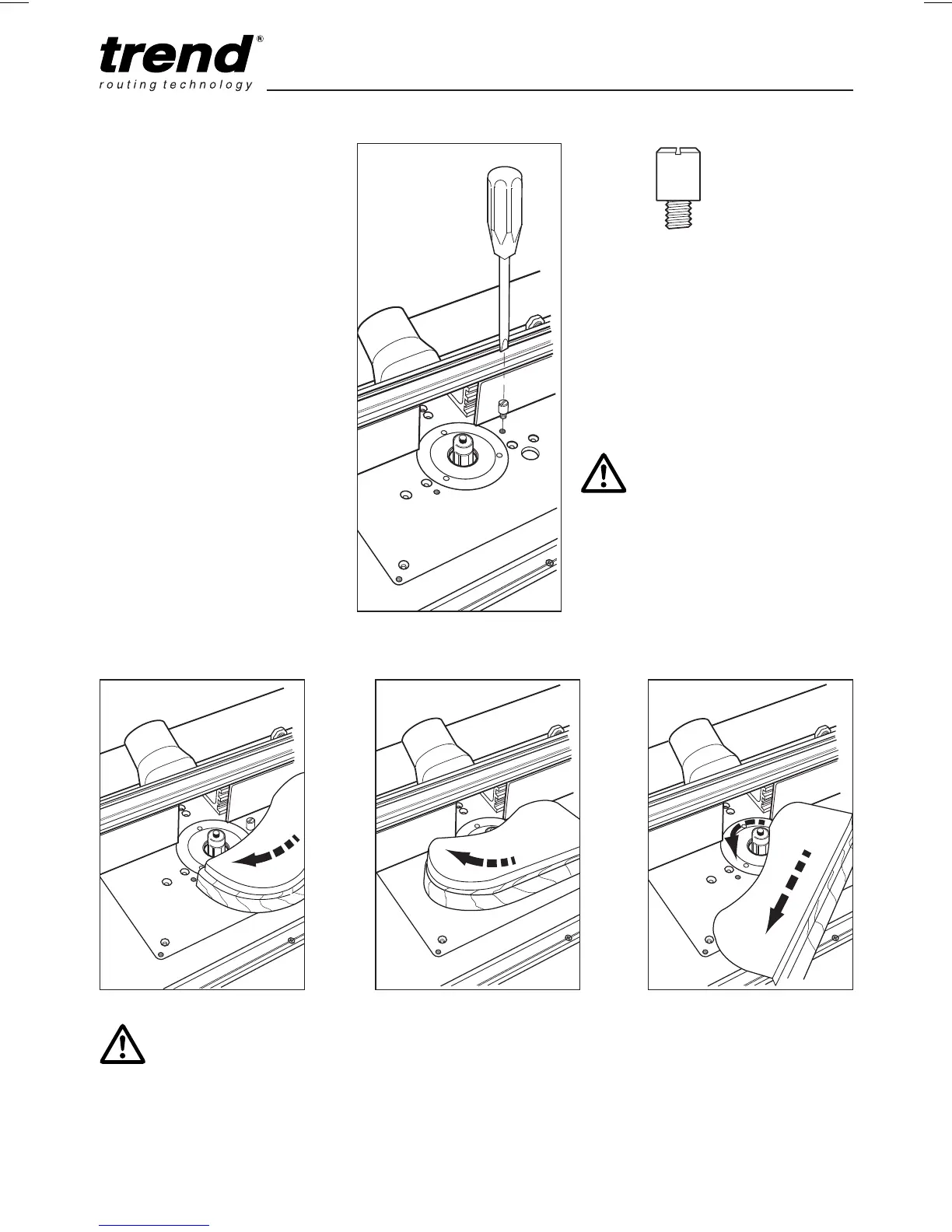
n Isolate from power supply.
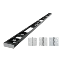
n Fit lead-on pin into threaded
hole using a slotted screw-
driver.
n Move back fence back.
n Fit self guided cutter.
n Fit top guard.
n Plug into power supply.
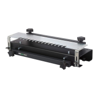
n Support component onto the
lead-on pin and swing into cut-
ter and contact bearing guide.
n Mould component.
n Switch off.
Lead-on Pin
WARNING: Guard removed
for clarity. Ensure guard
is fitted when using self
guided cutters.
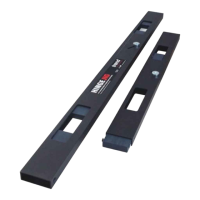
NOTICE: The lead-in pin can be
stored in the pin park hole in the
back fence when not in use.
x1