7EN
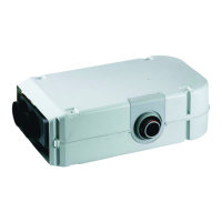
Truma E-Kit
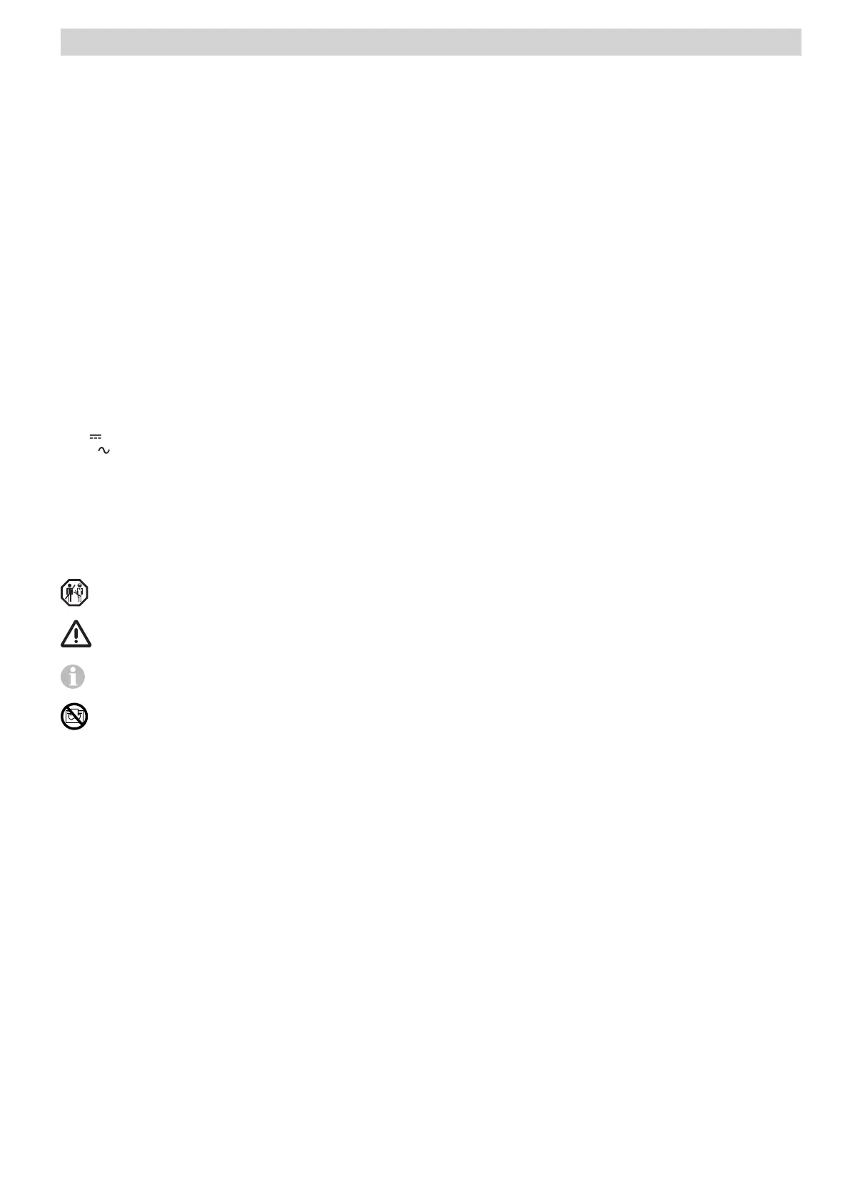
Symbols used
The appliance must only be installed and repaired by an
expert.
Symbol indicates possible hazards.
Note containing information and tips.
Danger of overheating! Do not cover the heater.
Proper use
The appliance is approved solely for installation and operation
in “caravans” of vehicle class O, “motor homes” (“motor cara-
vans” of vehicle class M1 and “mobile homes”.
Safety instructions
In order to ensure that the equipment works
properly and to avoid damage, only power
supply sources with a purely sinusoidal wave-
form (e.g. voltage converter, generator) and
without voltage peaks must be used.
If this appliance’s power supply line is dam-
aged, it must be replaced by the manufactur-
er, the manufacturer’s Customer Service or
a similarly qualified person so as to prevent
hazards.
A water pipe may only be routed at a distance
of 1.5 m from the heater at the warm air duct.
In particular, the following will render warranty
and guarantee claims void and lead to exemp-
tion from liability claims:
– Modifications to the appliance (including
accessories),
– Using replacement and accessory parts oth-
er than original Truma parts,
– Failure to follow the installation and operat-
ing instructions.
The appliance may be operated only with
appropriate Truma control panels and
accessories.
The appliance’s operating permit, and conse-
quently also the vehicle’s operating permit in
some countries, are also rendered void.
Table of contents
Symbols used ..................................................................... 7
Proper use ........................................................................... 7
Safety instructions ............................................................ 7
Installation instructions
Scope of delivery ............................................................... 8
Optional accessories ......................................................... 8
Selecting a location ........................................................... 8
Dimensions .......................................................................... 8
Installation position ............................................................... 8
Preparation .......................................................................... 9
Installation variants ........................................................... 9
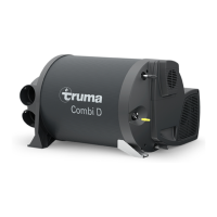
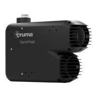
Mounting on the Truma VarioHeat ....................................... 9
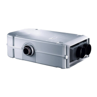
Installation into the warm air distributor ............................... 9
Separate installation space ................................................... 9
Installing the Truma E-Kit in the warm air distribution ......... 9
Warm air distribution ...................................................... 10
Connect the duct VR 80 to the Truma E-Kit ....................... 10
Connect the elbow BG 80 to the duct adapter ................... 10
Electrical connection ....................................................... 10
12 V voltage supply ......................................................... 11
230 V voltage supply ...................................................... 11
Truma E-Kit control unit ................................................. 11
Function check ................................................................. 11
Technical data ................................................................... 11
 Loading...