9EN
Preparation
Install the Truma VarioHeat as specified in the installation
instructions.
Securely screw (2.5Nm) the mounting bracket(1) onto the
Truma E-Kit with two PT screws (5x14mm), with a spring
washer in between for each screw (Figure 05 I/II).
Truma E-Kit
Truma E-Kit
I
II
11111
Figure 5
Installation variants
The Truma E-Kit can be installed directly on the Truma VarioHeat
or in the warm air distribution of the Truma VarioHeat.
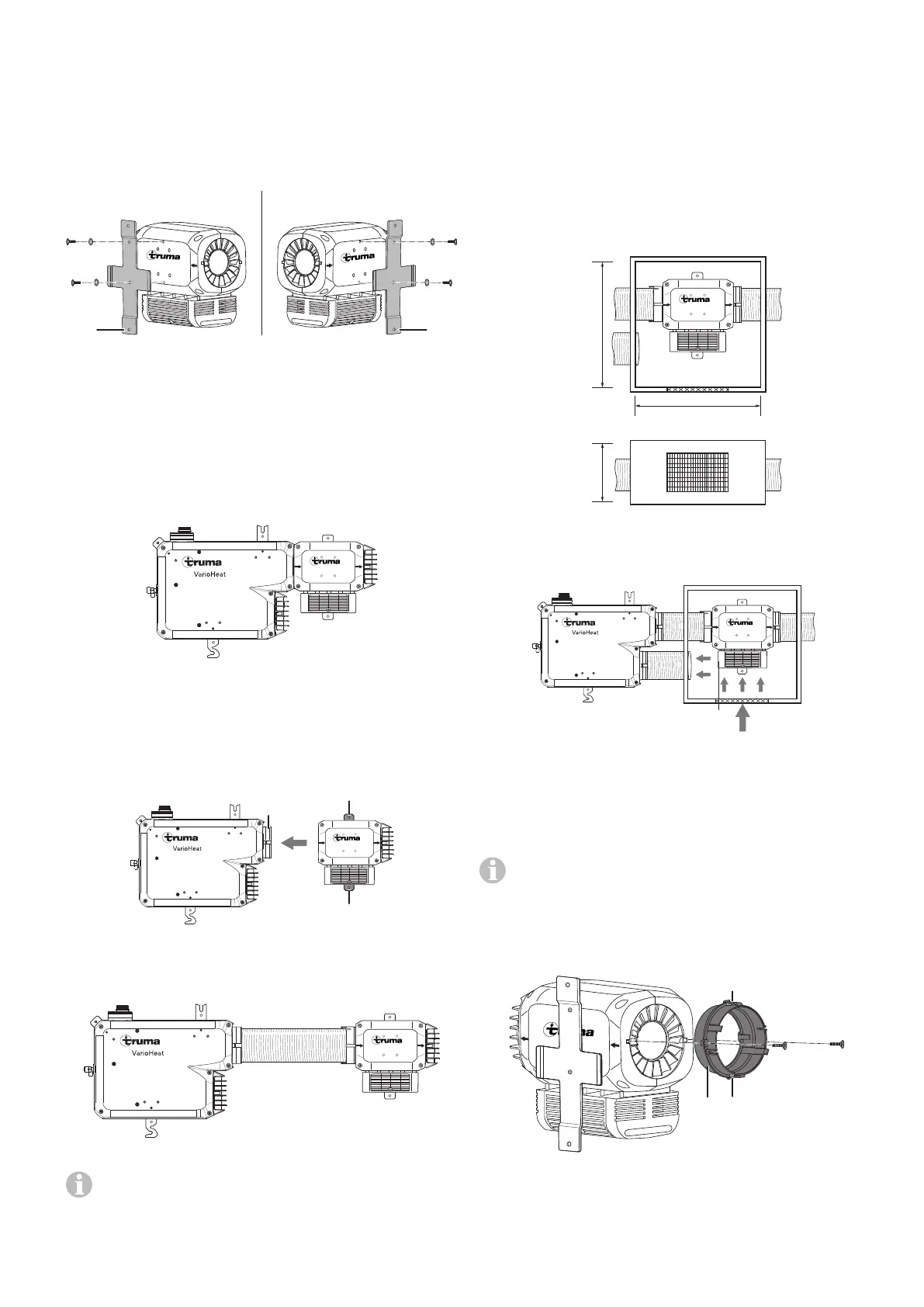
Mounting on the Truma VarioHeat
Truma E-Kit
Figure 6
Push the Truma E-Kit as far as possible onto the warm air out-
let(2) of the Truma VarioHeat and securely screw the mount-
ing bracket(1) onto the vehicle floor or wall with two screws
(5.5x25mm). The arrows on the Truma E-Kit indicate the hot
air’s direction of flow.
1
1
2
Truma E-Kit
Figure 7
Installation into the warm air distributor
VR 80
Truma E-Kit
Figure 8
Additional information and notices in the Warm air dis-
tribution section must be followed.
Separate installation space
When installed in the warm air distribution, the Truma E-Kit
can be fitted in a separate installation space. The circulated
air intake of the Truma VarioHeat must be routed through the
installation space of the Truma E-Kit. The circulated air intake
must have one large or several small openings with a total
area of at least 150 cm² between the living compartment (not
the rear storage space) and the installation space. If a grille
(not supplied) is installed, the same requirements must be
complied with for drawing in air in terms of the cross-section-
al area through which flow occurs (150cm²).
Minimum dimensions of the installation space (in mm)
340
360
140
Truma E-Kit
Figure 9
The circulating air(U) must flow into the installation space on
the electronics housing(E) side.
E
U
Truma E-Kit
Figure 10
Installing the Truma E-Kit in the warm air
distribution
If the Truma E-Kit is installed in the warm air distribution,
a duct adapter (available separately) must be used.
Insert the duct adapter(3) into the Truma E-Kit until both the
catches(4) have engaged in the housing. In addition, the duct
adapter(3) can be securely screwed onto the recesses in the
housing of the Truma E-Kit with two screws (2.9x13mm).
Truma E-Kit
3 4
4
Figure 11
Insert the duct VR 80 into the warm air outlet (2) of the
TrumaVarioHeat and into the Truma E-Kit as far as possi-
ble, and securely screw the mounting bracket (1) onto the
vehicle floor or wall with two screws (5.5x25mm). During
installation, pay attention to the hot air’s direction of flow.