22
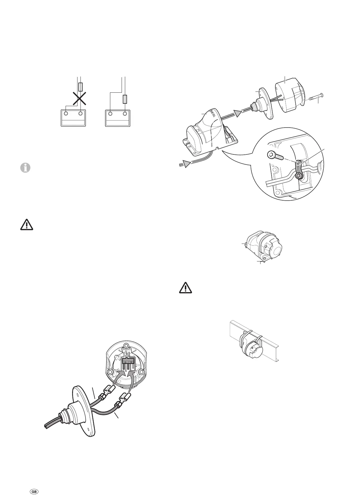
Connecting the battery
Liquid electrolyte batteries must be installed in a separate box
with ventilation leading to the outside. The fuse in the positive
lead must be connected outside the box. A separate box is
not required for gel or AGM batteries. Pay attention to the bat-
tery manufacturer’s installation instructions.
The outgoing lines from the terminals must be routed with a
gap between them until after the fuse in the positive lead.
+
-
+
-
Fig. 19
Route the battery connector cables (only use the original
Truma cables supplied) to the control unit and attach them
securely using the clips and screws provided.
The battery connector cables must not be extended.
They must be routed separately from the motor cables,
and must not run over the control unit.
Route battery connector cables so that they do not chafe (par-
ticularly at leadthroughs through metal panels). Use suitable
protective leadthrough bushing to prevent damage to cables.
Connect battery connector cables to the existing battery ter-
minals (red = positive, black = negative).
Incorrect polarity will destroy the electronics/control
unit.
The connection to the control unit (as per the connecting
diagram) must be made in the order: nut, battery connection
ring eyelet, nut (torque M6 = 6 Nm).
Connect fuse in the positive lead (150 A) near the positive
terminal.
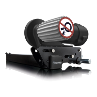
Connecting the safety socket
Lead the provided 2-wire cable with the flat connectors
through the socket holder (g) and the rubber sleeve (h).
If necessary, open cover and push socket connection out of
socket housing (i).
Connect 2-wire cable with flat connectors to micro switch.
RD / BK
BK
Fig. 20
If necessary, insert socket connection back into socket hous-
ing (i).
Screw socket housing (i) to socket holder (g) using 3 sheet
metal screws (j). (Several positions are possible by selecting the
mounting holes at the socket holder and rotating the rubber
seal)
Lead cable loosely through the strain relief (k) and screw in
place with the 2 sheet metal screws. Depending on the instal-
lation situation, the cable can be led out of the socket holder
through one of the three recesses.
j
(3 x)
h
g
PT 4 x 10
k
Fig. 21
Secure safety socket to the (plastic) shaft cover of the caravan
with 4 screws, nuts and washers.
M4 x 16
(4 x)
Washer 4.3
Fig. 22
No holes must be drilled in the chassis.
Alternatively, the safety socket can be secured using the two
clips.
Fig. 23
Route both wires to the control unit (shortening them if neces-
sary) and connect them to the connector block as shown in
the connecting diagram.
Re-check whether all cables are correctly connected, attached
using the provided clips and cannot chafe.
 Loading...