15
Fig. 23 Remove 6 screws from lower inner cover
5. Place the printer upside down and unscrew the two screws of the hinge holder on
the lower cover. Unscrew the screw of the memory card cover.
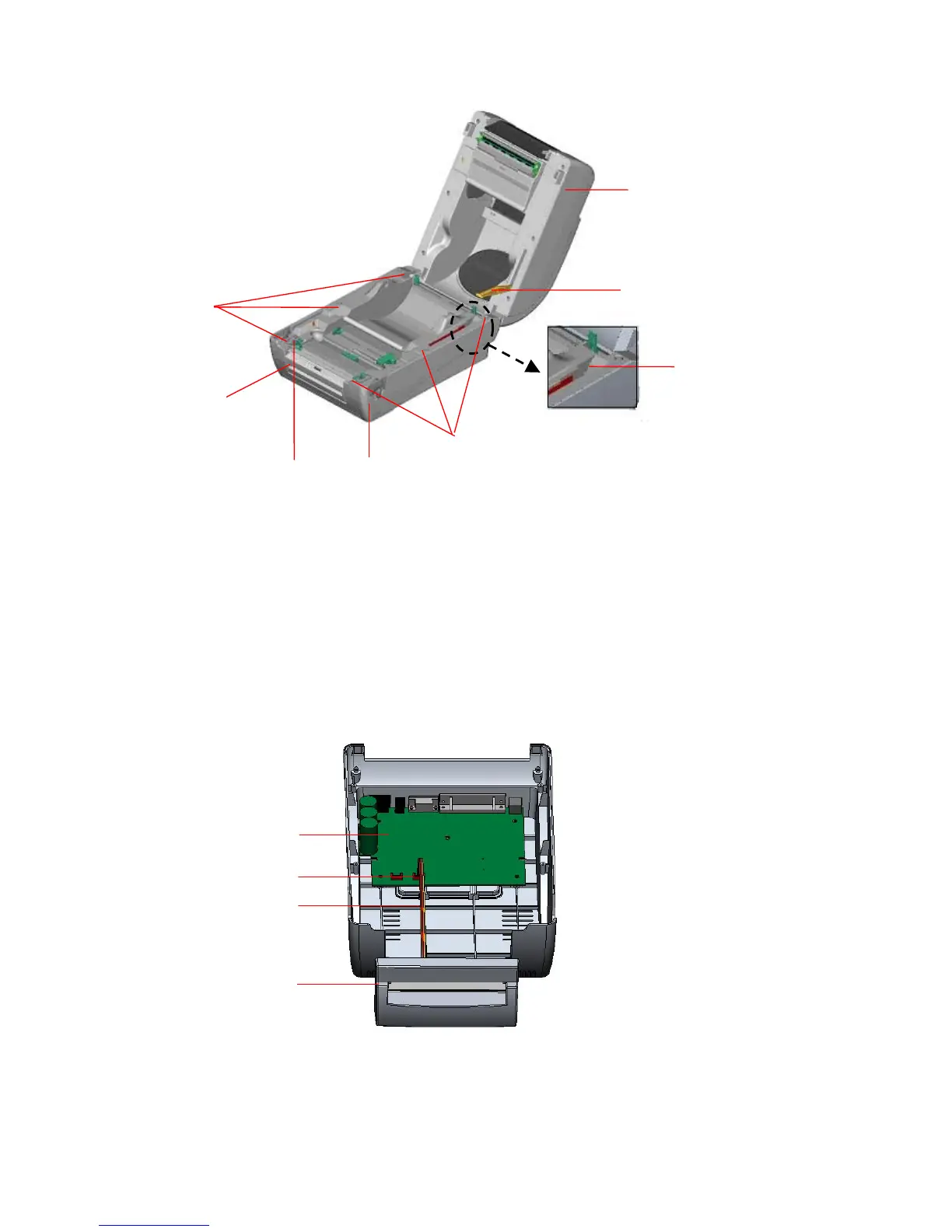
6. Use both thumbs to hold the lower cover and index fingers to lift up the top cover
open levers to separate the lower inner cover and the lower cover.
7. Arrange the cable through the bezel. Connect the cutter module cable to the 4-pin
socket on printer PCB.
Fig. 24 Cutter module installation
PCB
4-pin Socket
Cutter Cable
Cutter
Screws
Top Cover
Screws
Top Cover Support
Flute
Lower Cove