EasyManua.ls Logo

TSC TTP-343 Plus

TSC TTP-343 Plus
72 pages
To Next Page IconTo Next Page
To Previous Page IconTo Previous Page
Loading...
47
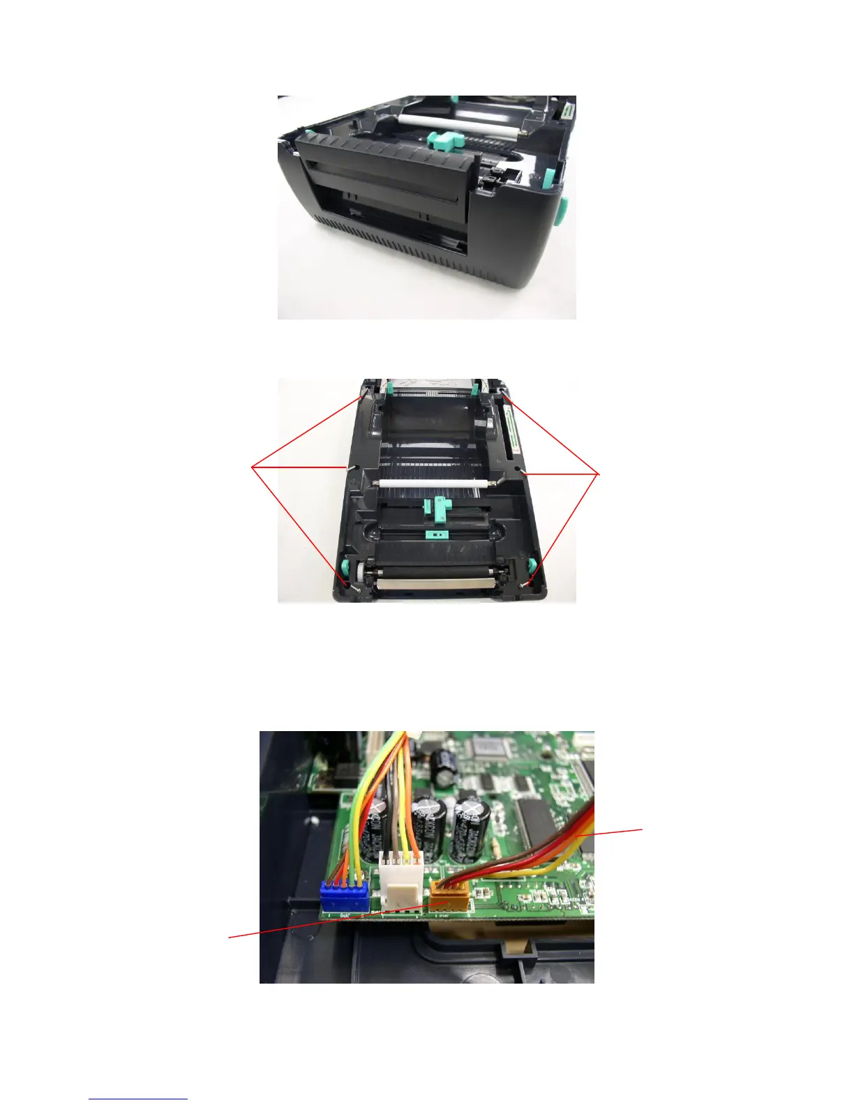
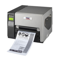
7. Remove the 6 screws in lower inner cover.
8. Lift up the lower inner cover from the Lower Cover.
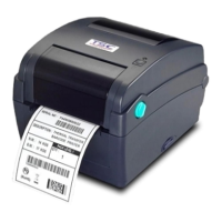
9. Install the 4 pin connector of the cutter onto JP38 on the main board. Pull the wire
of the 4-pin connector through the slot of lower inner cover front side. Then, put
back the lower inner cover.
Location
JP38
Screws
Screws
Wire of the 4-pin
connector

Other manuals for TSC TTP-343 Plus

Related product manuals