V02.00 | 2019/10
23
7 Connecting
7.1 Connecting the device to Ethernet
For the connection to Ethernet the device has an integrated auto-crossing switch with two 4-
pole, D-coded M12 x 1-Ethernet-connectors. The maximum tightening torque is 0.6 Nm.
Fig.14: M12 Ethernet connector
Connect the device to Ethernet according to the pin assignment below.
v
4
1
3
2
P1, P2
1 = TX +
2 = RX +
3 = TX –
4 = RX –
flange = FE
Fig.15: Pin assignment Ethernet connectors
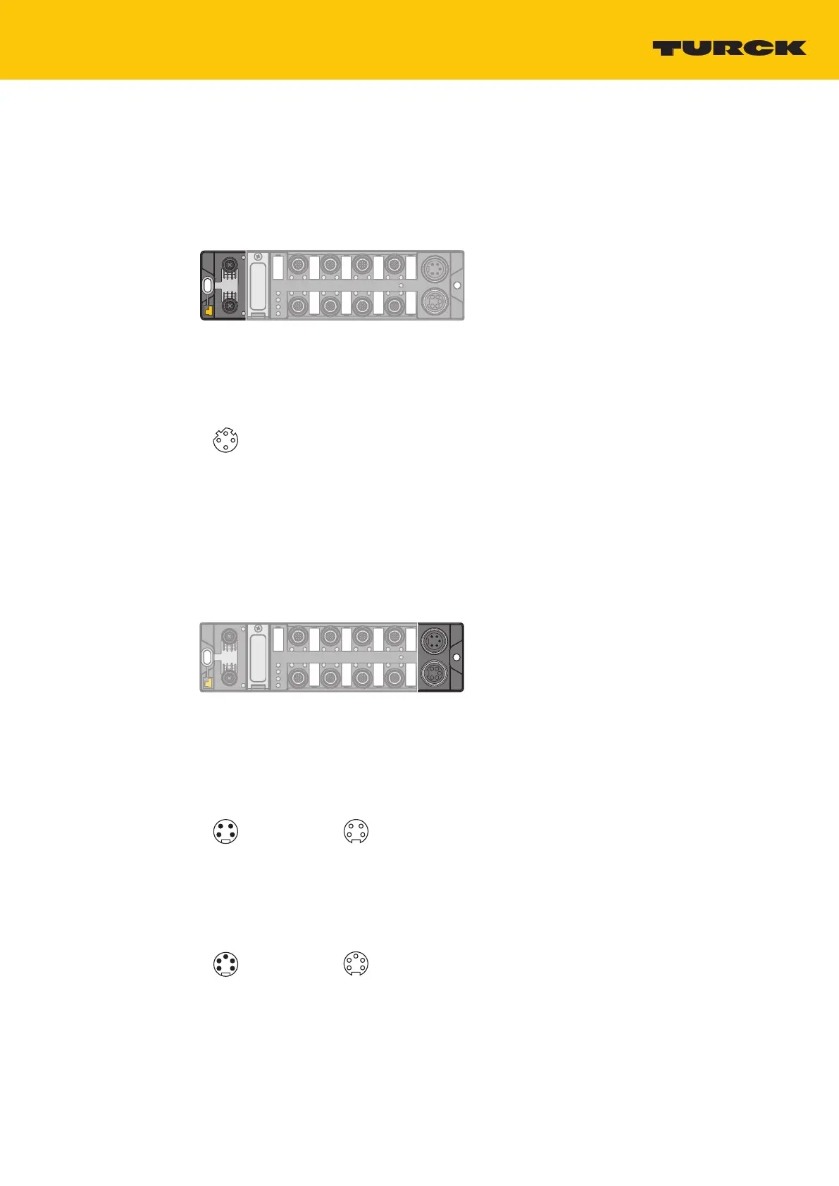
7.2 Connecting the power supply
For the connection to the power supply, the device has two 5-pin 7/8" connectors. The power
supply connectors are designed as 4-pole (TBEN-L4) or 5-pole (TBEN-L5) 7/8" connectors. V1
and V2 are galvanically isolated. The maximum tightening torque is 0.8 Nm.
Fig.16: 7/8’’ connector for connecting the supply voltage
Connect the device to the voltage supply according to the pin assignment below.
w v
1
2
3
4
1 RD = 24 VDC V2
2 GN = 24 VDC V1
3 WH = GND V1
4 BK = GND V2
1
2
3
4
X1 X2
Fig.17: TBEN-L4-… – pin assignment power supply connectors
1 BK = GND V2
2 BU = GND V1
3 GNYE = FE
4 BN = 24 VDC V1
5 WH = 24 VDC V2
3
4
5
2
1
w v
3
4
5
2
1
X1 X2
Fig.18: TBEN-L5-… – pin assignment power supply connectors

 Loading...