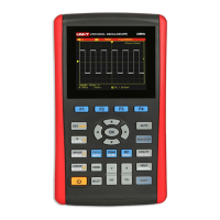
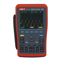
UTD1000L User Manual
13
FFT represents adjusting the FFT operation
waveform
2. Trigger coupling mode display are as follows:
AC trigger coupling mode
DC trigger coupling mode
HF high frequency trigger coupling mode
3. Reading indicates the edge trigger level
position
4. Trigger status display are as follows
ARMED oscilloscope is collecting pretrigger data
under the status all triggers would be neglected
READY oscilloscope had collected all pretrigger
data and is ready to accept trigger
TRIG ED oscilloscope had found a trigger and
is collecting the data after triggered
STOP oscilloscope ceased collecting waveform
data
AUTO oscilloscope is under automatic mode and
collecting waveform under the non-trigger status
SCAN oscilloscope collects and displays
waveform continuously under the scanning
mode
5. Display time reading of trigger point to the
center scale
6. Symbols indicate power supply modes as
follows
7. Symbols on the screen indicate ground baseline
8. 1 symbol indicates the channel probe
multiplying power is 1
9. Reading displays main time base setting
10. Home computer connection symbol
11. Reading displays present vertical scale
coefficient.
12. Waveform opposite phase symbol
13. The reading indicates the shift value of
channel reference symbol relative to screen
horizontal midline.
.
:
,
;
;
'
;
;
;
.
:
;
;
Battery power supply used by oscilloscope
DC adapter power supply used by oscilloscope

 Loading...


