9
Chapter 2: Mounting
This chapter gives detailed panel mounting instructions.
Before You Begin
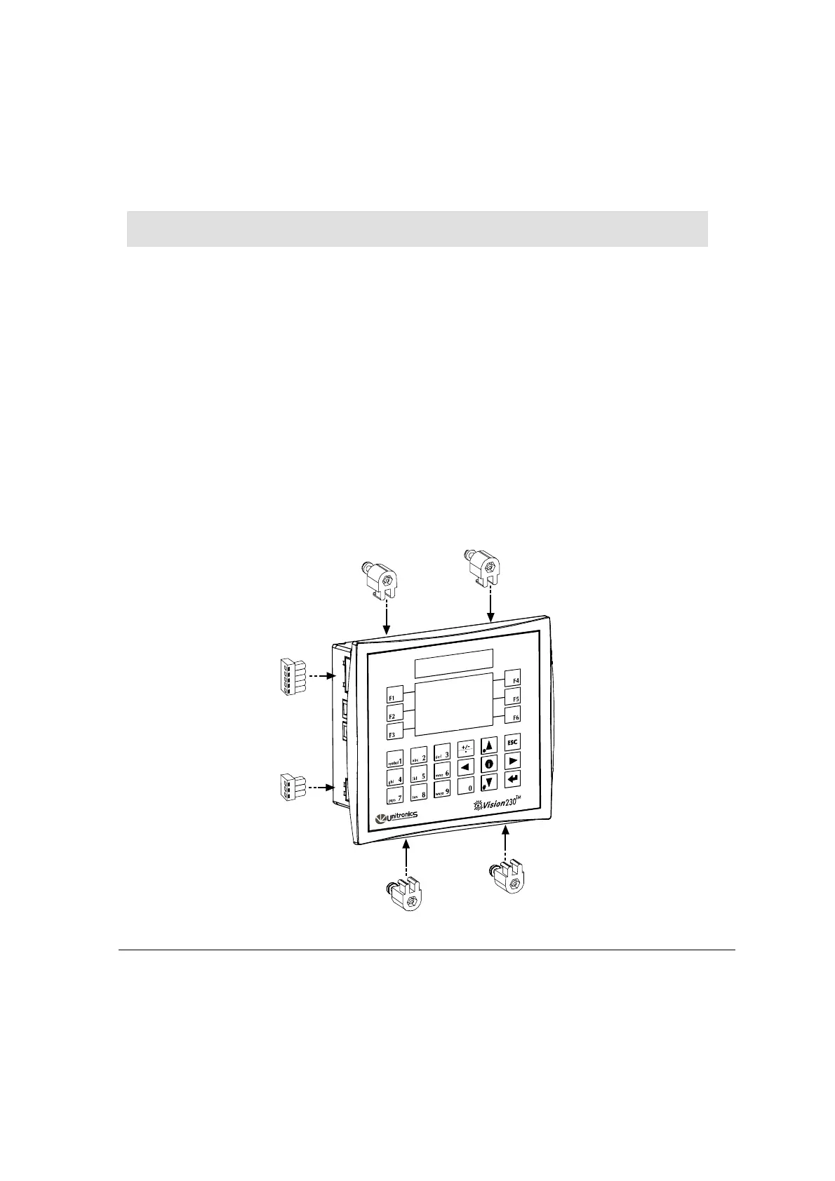
Before you begin installation procedures, check the contents of the controller kit. Standard kits
contain the controller, a 3-pin power supply connector, a 5-pin CANbus connector, and 4
mounting brackets, each with a screw inserted. These elements are illustrated in Figure 2
below. Other items in the kit include an envelope containing a wire that is ended by a ring
cable shoe and other hardware that may be used to earth the controller’s power supply. The kit
also includes a rubber seal already seated in back of the operating panel, a CANbus network
termination resistor; a CD-ROM containing VisiLogic software for programming the
controller, a communication cable, this manual, and two sets of keyboard slides which you can
use to label the keyboard keys. Note that one set of slides is already installed in the operating
panel.
Some kits may also include installed Snap-in I/O modules and documentation.
Figure 2. Vision Connectors and Mounting Brackets