Vision 230/260/280 User Guide
16
6. Strip the wire to a length of 7±0.5 mm (0.250–0.300 inches).
7. Unscrew the terminal to its widest position before inserting a wire.
8. Insert the wire completely into the terminal to ensure a proper connection according to
the figure below.
9. Tighten enough to keep the wire from pulling free.
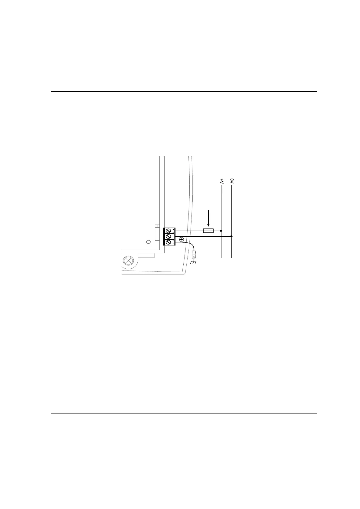
+V
0V
12 VDC
or 24 VDC
Circuit
protection
device
Figure 7. Power Supply Wiring
Earthing the Power Supply
To maximize system performance, avoid electromagnetic interference by:
• Mounting the controller on a metal panel.
• Earthing the controller’s power supply by connecting the chassis signal to the panel as
shown in Figure 6, page 14, and connecting the tapered end to the power supply as
shown in Figure 7 above.
Note: The wire used to earth the power supply must not exceed 8 cm in length. If your conditions
do not permit this, do not earth the power supply.