19
Chapter 5: Communications
This chapter contains guidelines for communications connections. All Vision controllers
comprise 2 RS232 ports and a CANbus port. Certain models offer other communication
options such as RS485.
RS232
Via the RS232 serial ports, you can:
• Download programs from a PC.
• Communicate with RS232 devices.
You can, for example, use your PC to access a networked controller via its RS232 port.
You can then view, read, and write data into any unit. RS232 also allows you to view
the network via a SCADA program.
The RS232 interface is via RJ-11 type serial ports located on the side of the controller, shown
in Figure 6, page 14.
• Turn off power before making communications
connections.
• Do not connect the controller directly to a telephone or
telephone line.
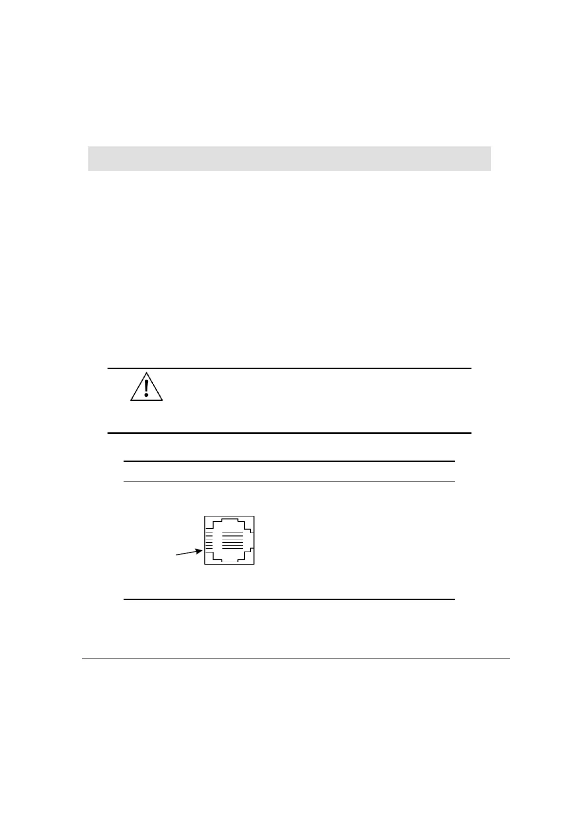
Table 1: RS232 Port Pinout
Diagram Pin Number Function
1 DTR signal*
2 0V reference
3 TxD signal
4 RxD signal
5 0V reference
Pin #1
6 DSR signal*
*Standard programming cables do not provide connection points for pins 1 and 6.