Vision 230/260/280 User Guide
20
Caution
• Signals are related to the controller’s 0V; this is the same
0V used by the power supply.
• The RJ-11 type serial port located on the side of the
controller must always be used with an appropriate
adapter.
• The RS232 serial port is not isolated.
Downloading Your Program
You can download programs via a direct cable connection between your PC and the controller.
The cable should not exceed 3 meters in length.
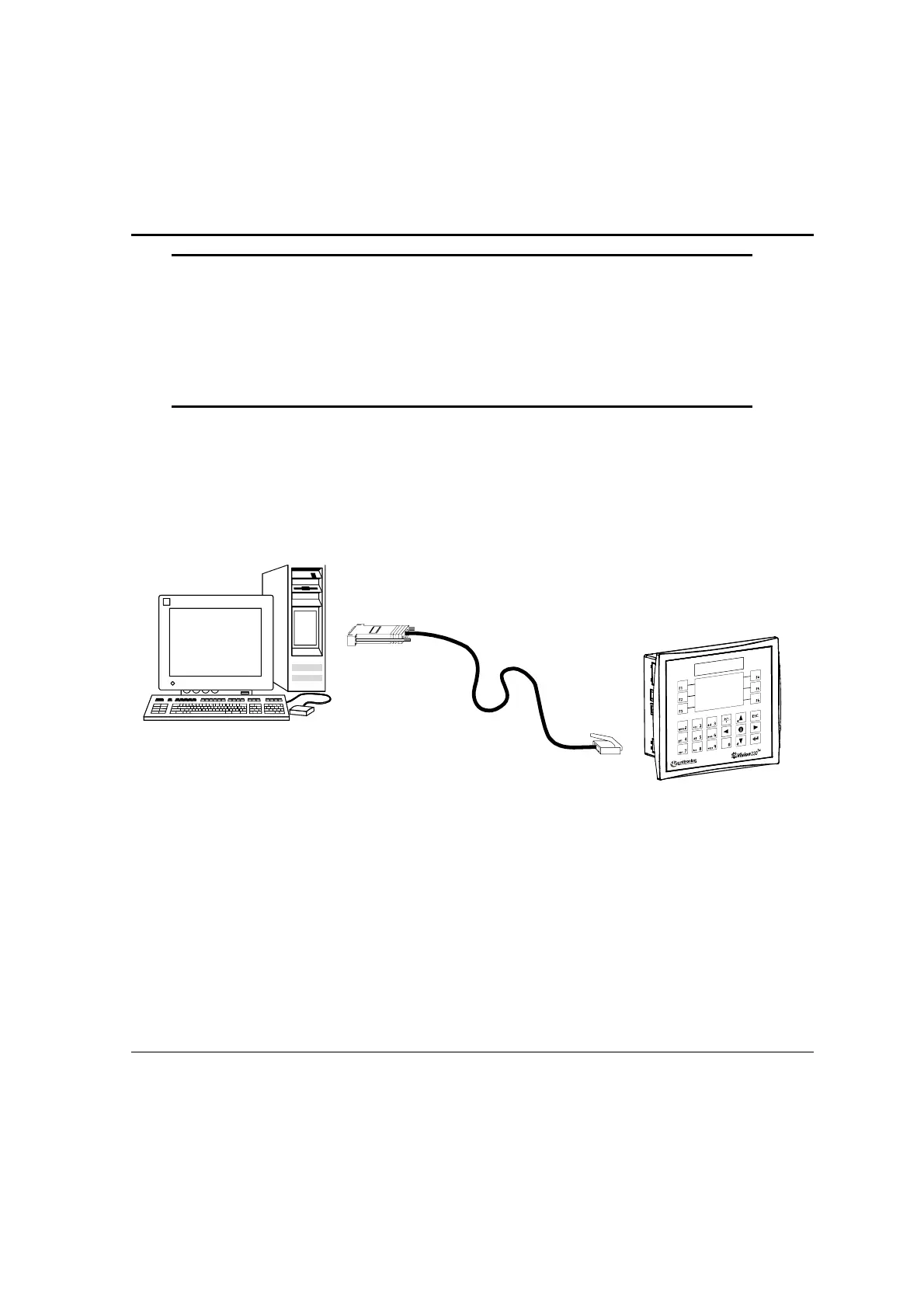
Connecting the Controller to the PC
• Connect the controller to your PC using the communication cable as shown below.
Figure 9. Connecting the PC to the Controller
CANbus
The CANbus port is located on the side of the controller, as shown in Figure 6, page 14. Via
this port, you can create a decentralized control network of up to 63 controllers. This is
sometimes called a multi-master network. In such a network, CANbus enables inter-PLC data
exchange.
Unitronics’ CANbus control network is run by a separate isolated power supply that is not part
of the network power supply.