4. After disconnecting the wires gently remove black flexible flat ring with a tiny screwdriver
and twist it around the joint housing.
5. Slide back the black Teflon ring. screws become visible. Loosen the screws.
6. Pull the Base joint and Shoulder joint gently apart.
Assemble
For details and photos please see: General Guidance to Separate Joint from Counterpart
WARNING
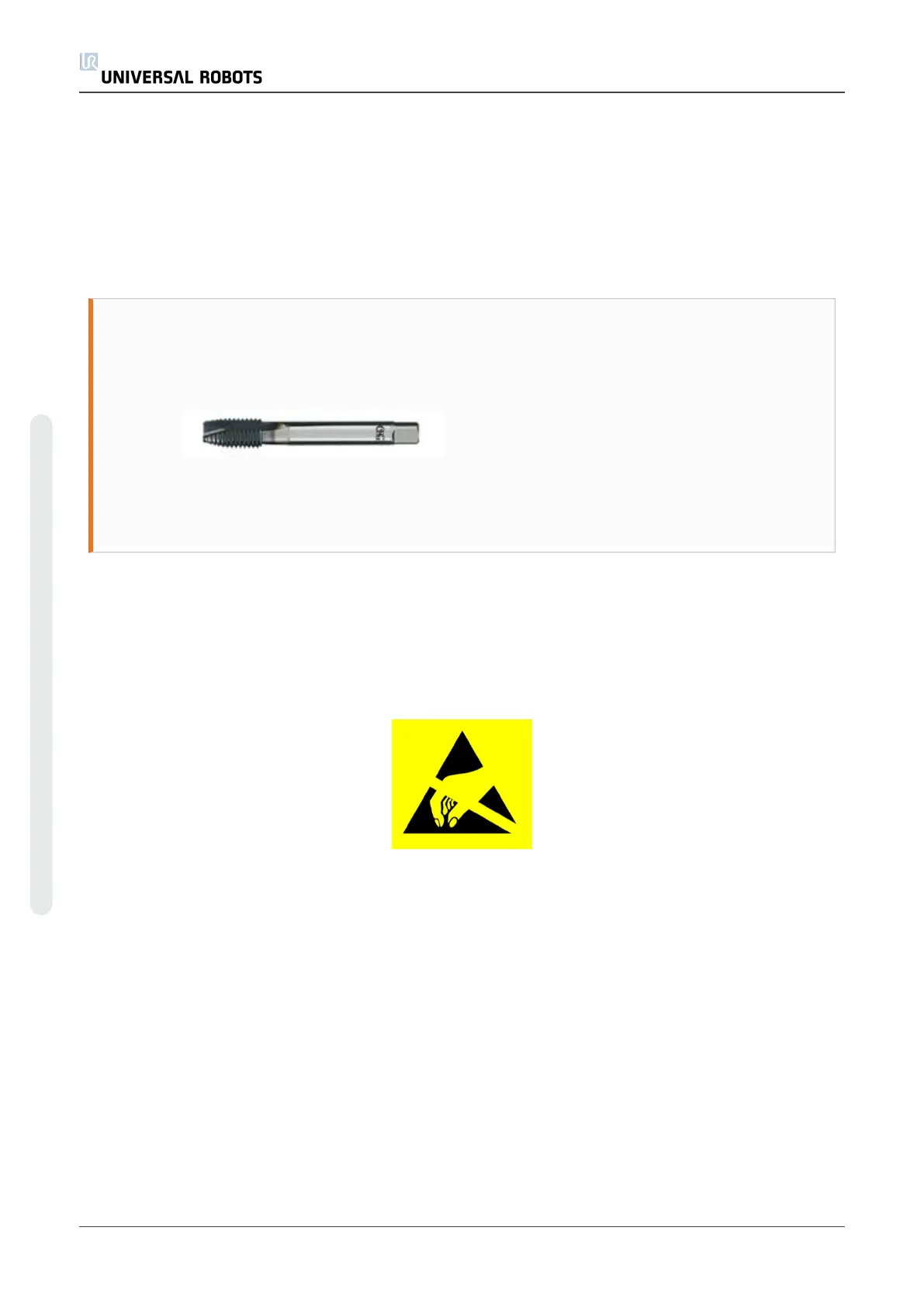
Remove Loctite residue inform screw holes using an M3 (M4 for Size 2) tap tool
for threads before assembling the joint to get the correct torque on the new
screws.
Always use new pre-coated screws where possible. If you must assemble with
old screws carefully clean the screws and apply Loctite 243 to the threads before
assembly.
1. Orientate the Base joint and Shoulder joint according to the marks and gently push them
together.
2. Gently tighten the screws, and then tighten in cross order with 3.0Nm.
3. Slide the black Teflon ring into place and gently put the flat ring back on top of the Teflon
ring.
4. Connect ESD wristband.
5. Twist the communication cable 1.5 to 2 full rounds before it is connected to reduce
electrical noise in the system.
1 x red wire = 48V DC
1 x black wire = GND
White and black = bus connector
6. After connection of the wires then mount the blue lid and tighten with 0.4Nm.
7. Proceed to Dual Robot Calibration for instructions on how to calibrate the robot.
5.2.8. Upper arm – Shoulder joint
Disassemble
UR3 30 Service Manual
5.Service and Replacement of Parts
Copyright © 2009–2021 by UniversalRobotsA/S. All rights reserved.