All rights reserved 86 Servicemanual_UR3_en_rev3.1.2
5.2 LED indicators and Fuses on Safety Control Board
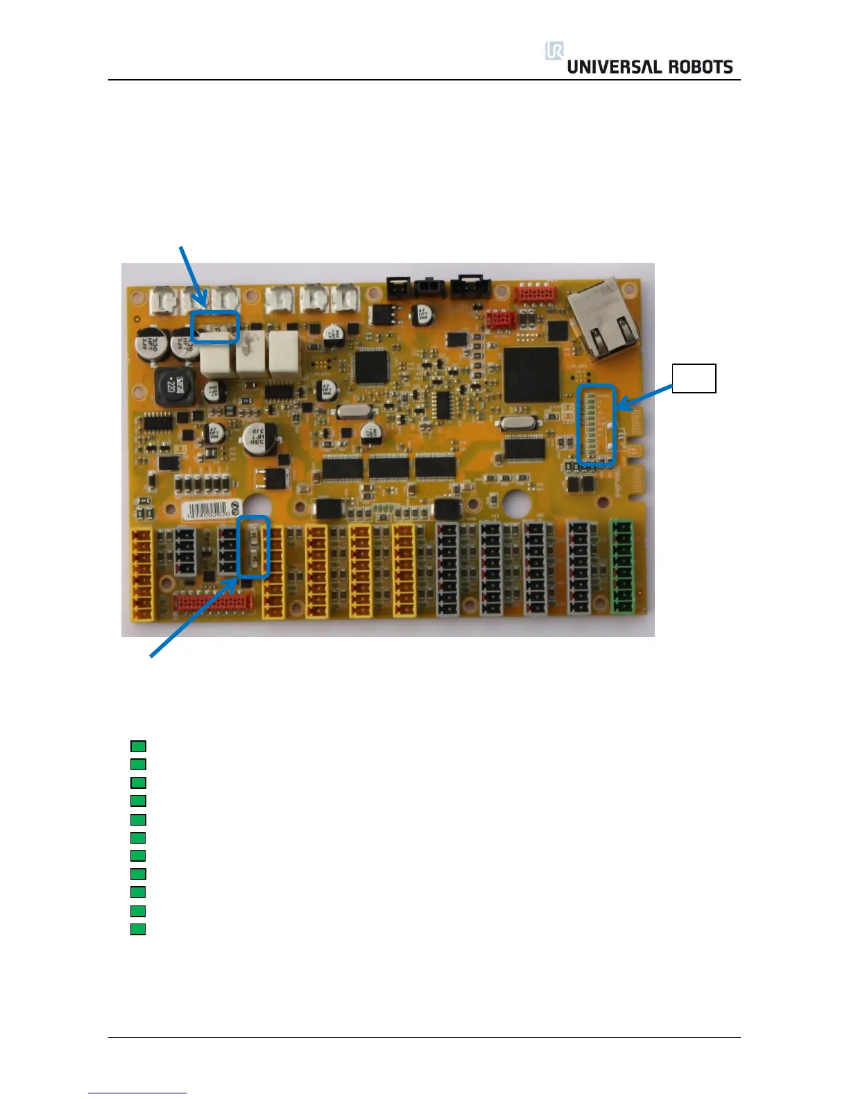
Safety Control Board (SCB)
The 5 A fuse “48 V” protects all 48 V for over current in the system inclusive Euromap.
This information is only for troubleshooting. Do NOT replace the fuse on any circumstances.
Do ONLY replace the SCB with a new tested board.
Fuse 24 V: 2 fuses 5 Amp in parallel for the DI/DO 24 V supply on the safety control board
no matter if the 24 V is from the controller or external power supply.
LED indicators:
12V-PSU On when the power plug is connected.
12V System: On when the power on has been activated
5V On when “12 V System” is on and indicate that 5 V is ok.
-4V On when “12 V System” is on and indicate that - 4 V to analog I/O is ok.
3V3A On when 5V is on and indicate 3.3 V for logic Safety circuit A
3V3B On when 5V is on and indicate 3.3 V for logic Safety circuit B
48V 48 V is present on the safety control board
24V 48 V is detected and ok, indicate that internal 24 V is present for I/O’s
R 48 V on robot arm
A Status for Logic A: a blink sequence
B Status for Logic B: a blink sequence