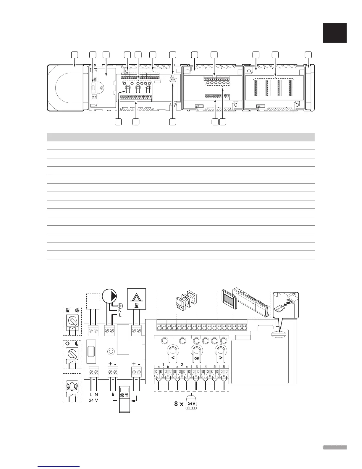
EasyManuals Logo
Home>Uponor>Heating System>Smatrix Base

Uponor Smatrix Base User Manual

Uponor Smatrix Base
132 pages
To Next Page IconTo Next Page
To Previous Page IconTo Previous Page
Page #121 background imageLoading...
Page #121 background image
17.3 Controller layout
E IG H G GJ L
F N F KD
CB MA
Item Description
A Transformer, 230 V AC 50 Hz power module
B Fuse (T5 F3.15AL 250 V)
C Optional inputs and outputs (pump and boiler management, and heat pump connection)
D Channel registration buttons
E LEDs for channels 01 – 06
F Quick connectors for actuators
G Bus connection terminals
H System bus connection terminals (Base PRO only)
I Power LED
J Uponor Smatrix Base Slave Module M-140 (optional slave module)
K LEDs for channels 07 – 12
L Uponor Smatrix Base Star Module M-141 (optional star module)
M End cap
N MicroSD card (Base PRO only)
17.4 Wiring diagrams
uPonor smatriX Bas e Pro Controller
GPI 1
GPI
GPI 2
GPI 3
AB+-AB+-AB+-AB -AB-
UK
CZ
DE
DK
EE
ES
FI
FR
HR
HU
IT
LT
LV
NL
NO
PL
PT
RO
RU
SE
SK
121
UPONOR SMATRIX BASE/BASE PRO · INSTALLATION AND OPERATION MANUAL

Table of Contents

Other manuals for Uponor Smatrix Base

Questions and Answers:

Question and Answer IconNeed help?

Do you have a question about the Uponor Smatrix Base and is the answer not in the manual?

Uponor Smatrix Base Specifications

General IconGeneral
BrandUponor
ModelSmatrix Base
CategoryHeating System
LanguageEnglish

Related product manuals