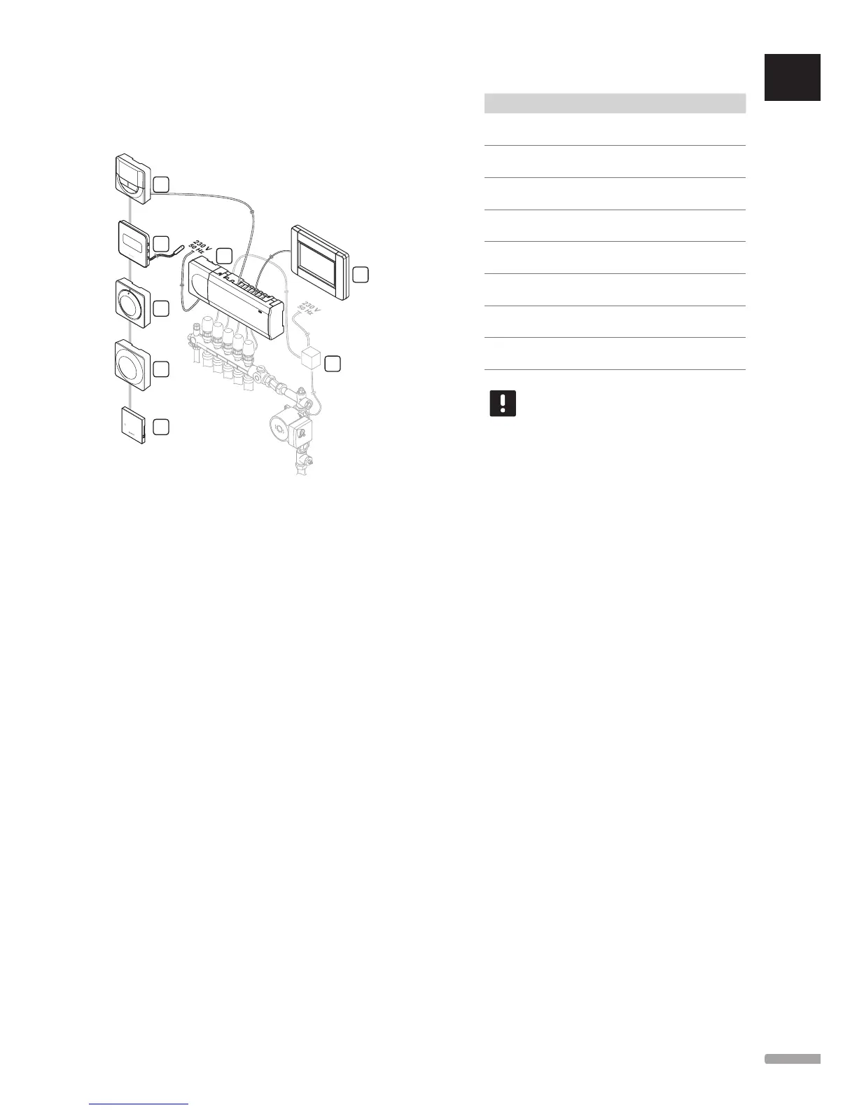
3.2 Example of a system
The illustration below shows Uponor Smatrix Base PRO
with several installation options and thermostats.
H
G
B
C
D
E
F
A
Item Description
A Uponor Smatrix Base PRO Interface I-147 (interface
I-147)
B Uponor Smatrix Base Thermostat Prog.+RH T-148
(digital thermostat T-148)
C Uponor Smatrix Base Thermostat D+RH Style T-149
(digital thermostat T-149) with floor sensor
D Uponor Smatrix Base Thermostat Standard T-145
(standard thermostat T-145)
E Uponor Smatrix Base Thermostat Public T-143
(public thermostat T-143)
F Uponor Smatrix Base PRO Room Sensor+RH Style
T-141 (room sensor thermostat)
G Uponor Smatrix Base Controller X-145 (controller
X-145)
H External connection box for pumps (third-party
product, just schematic example in illustration)
NOTE!
The floor sensor can be connected to
thermostats T-143, T-146, T-148, and T-149.
Floor temperature limitation together with
thermostats T-141 or T-143 can only be done
in a Base PRO system using an interface.
For example, the maximum limitation can
protect a sensitive floor covering from
exposure of too high temperature when there
is a high heating demand. The minimum
limitation can keep a tiled floor warm even
when there is a no general demand for heat
supply to the room.