43
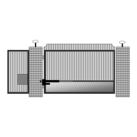
Electric Gate Lock
Part Number 070510
Suitable for solar and AC charged systems.
The Patriot Control Board will energize and
release a 12 vdc electric gate lock or de-
energize and release a magnetic gate lock 1
second before the gate or gates begin to open.
To activate the electric gate lock delay circuit
Turn DS2 switch 1 on. This also activates the Gate
Delay Feature on Dual Gate systems.
Connect the negative (12vdc-) wire from the
gate lock to J1 Common Gnd terminal
Connect the positive (12vdc+) wire from the
gate lock to J1 Solenoid Lock terminal.
For Dual Gates, see Gate Delay Feature Section 20, pg 32.
Magnetic Gate Lock
(Non-USAutomatic product)
Not suitable for solar charged systems. Suitable for AC charged systems.
To activate the magnetic lock delay circuit, turn DS2 switch 2 on. Connect the negative (12vdc-) wire
from the magnetic gate lock to J1 Common Gnd terminal. Connect the positive (12vdc+) wire from the
magnetic gate lock to J1 Solenoid Lock terminal.
NOTE: On dual gates with a magnetic gate lock, it is also necessary to turn DS2 switch 1 on to
activate the Gate Delay Feature.
For Dual Gates, see Gate Delay Feature Section 20, pg 32.
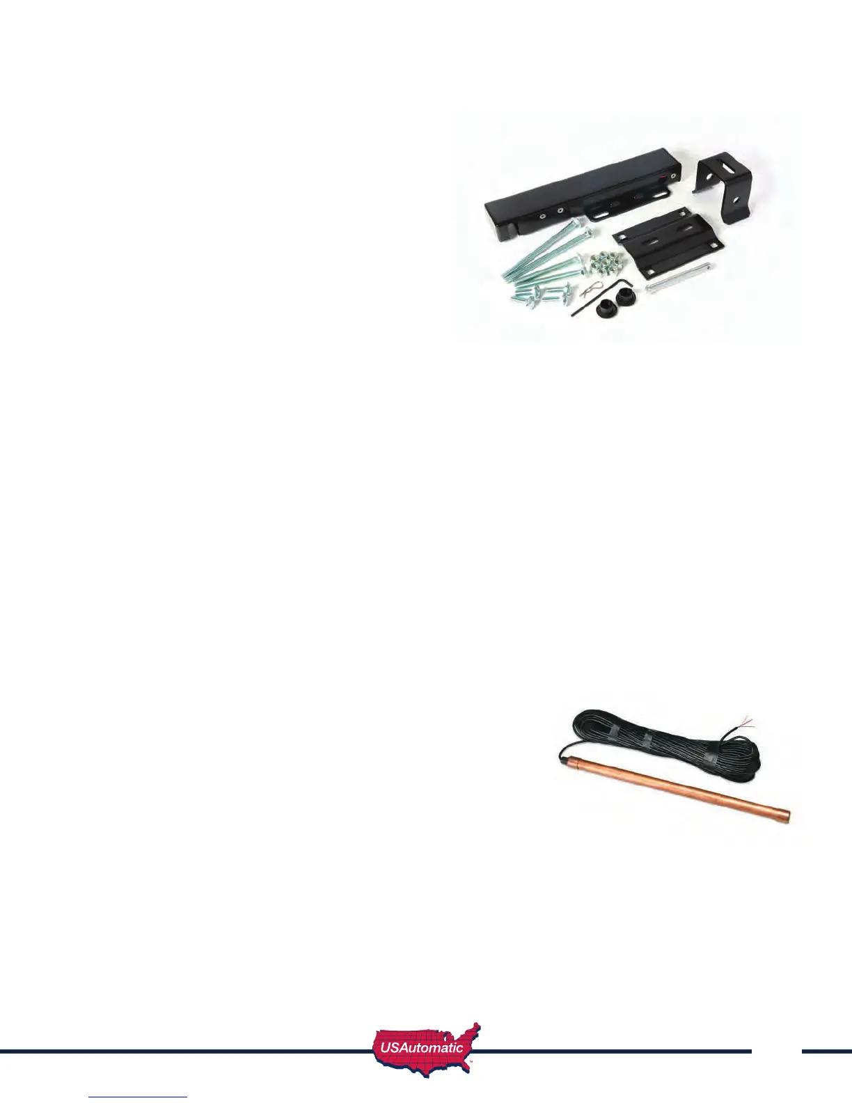
Exit Sensor (Solar friendly device)
Preferred Technologies CP-3-3W
Part Number 070305
The driveway exit sensor is a magnetic device that installs below
ground beside the drive. A magnetic eld is established which
when interrupted by a moving metal object will send a signal
to open the gate. This sensor is supplied with a 80 foot cable
and is typically installed inside the property beside the drive to
automatically open the gate when a car passes. This type of
sensor is not a safety device.
Sensor can be ordered with cable lengths that t the installation. (Standard 80’)
It is recommended to install this sensor and cable in PVC conduit.
Wire as follows: Red wire – connect to J2 pin 1
Shield (braided wire) – connect to J2 pin 2
Black wire – connect to J2 pin 9