45
The photo eye must be wired as shown and the correct dipswitches must be turned on for the PEPM
software to work correctly. Detailed instructions are below with illustration.
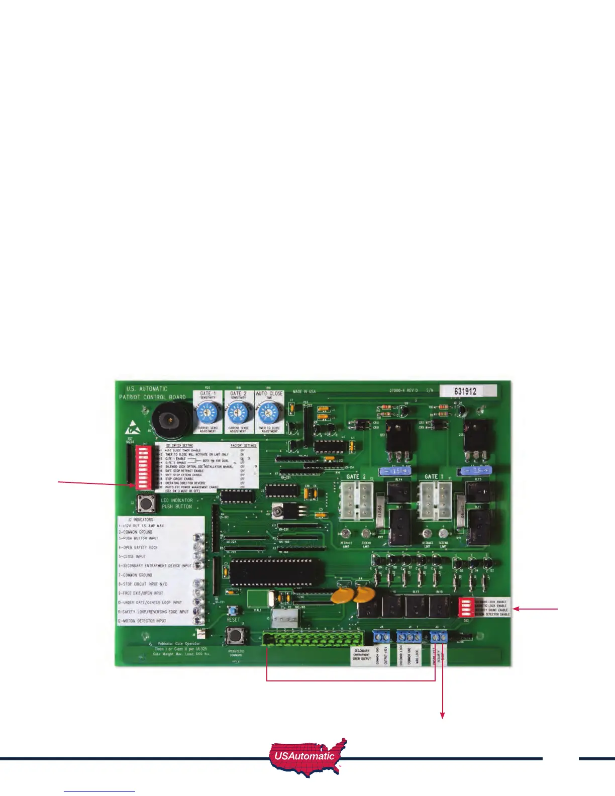
1. Connect jumper wire from J2 pin 1 to the left “Photo Eye / Security Shunt” terminal
2. Connect photo eye power +12 vdc to the right “Photo Eye / Security Shunt” terminal
3. Turn on dipswitch DS2 switch 3 in bottom right corner of control board (temporary while
adjusting beam)
4. Place gate in the open or mid travel position (allows power to the photo eye).
5. Wire the RX relay N/O contact from the photo eye to J2 pin 11.
6. Wire the RX relay common from the photo eye to J2 pin 2 or 7.
7. Wire the photo eye ground (power ground) to J2 pin 2 or 7.
8. Install Photo eye and adjust beam – verify proper operation.
9. Once installed turn OFF dipswitch, DS2 switch 3.
10. Turn ON dipswitch, DS1 switch 10 in the upper left corner of control board.
11. Test photo eye for proper operation, when gate is closing and beam is broken gate should stop
and reverse.
NOTE: Power is only applied to photo eye just prior to closing and when gate is going closed.
DS1 dip switch 10 -
Photo Eye Power
Management Enable
DS2dip switch 3 -
Security Shunt
Enable
Jumper wire from Photo Eye
/ Security shunt to J2 pin1
Photo Eye power +12 vdc