User's Guide _______________________________________________________________________
24 ___________________________________________________________________ M211510EN-E
Configuration and Wiring
To minimize working at height at the installation location, prepare the
transmitter configuration and wiring before climbing up.
1. Open the six screws that hold the transmitter cover.
2. Check that the DIP switches are set as desired. See section DIP
Switches on page 31.
3. Route the power and signal cable to the screw terminals and
connect the wires. Refer to section Wiring on page 27.
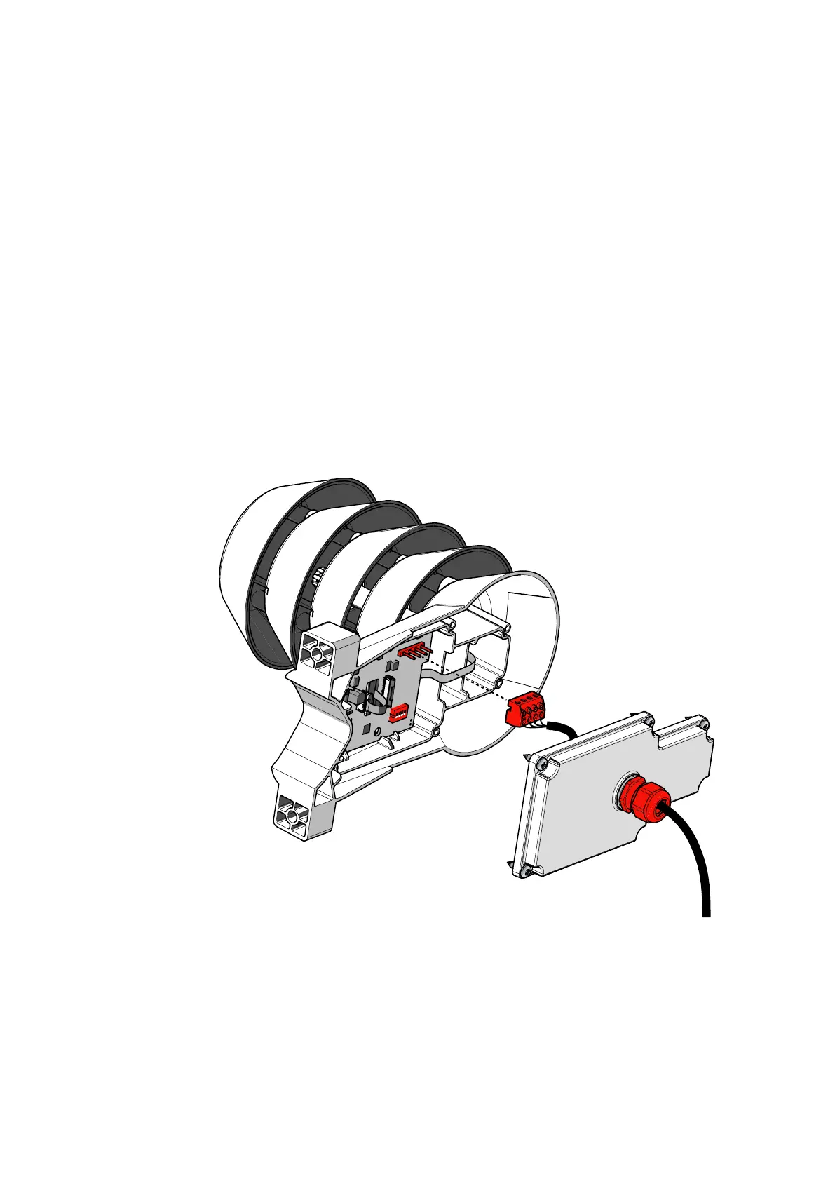
4. Disconnect the screw terminal block by pulling it away from the
component board.
5. Adjust the length of cable between the cable gland and the terminal
block. Make the cable short enough to close the cover without
leaving a cable loop in the transmitter.
6. Tighten the cable gland. Leave the cover off for now.
1304-059
Figure 14 Location of DIP Switches and Screw Terminal

 Loading...


