User's Guide _______________________________________________________________________
166 __________________________________________________________________ M210243en-A
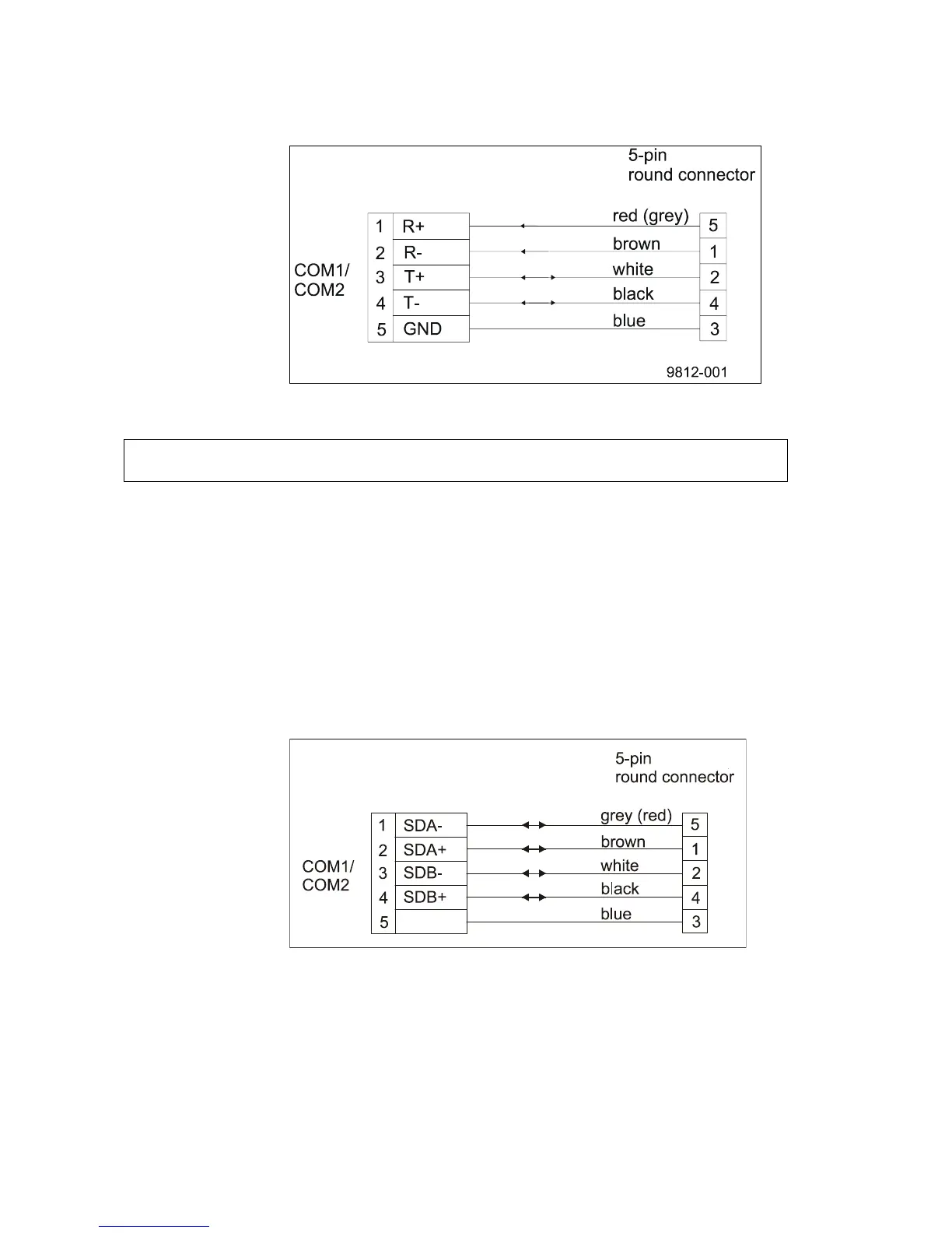
Figure 124 DSI485A Wiring Diagram
NOTE
In 2-wire mode, only T+ and T- pins are used.
DSI486
Channel A is always used in RS-485 -mode. In 2-wire RS-485, both
transmitted and received data is sent via this channel. In 4-wire RS-
485 this channel can either transmit or receive depending on the
configuration. Jumper X4 defines the line terminating resistor for the
data channel A. Remove the jumper X4, if you do not need the
terminating resistor of DSI486. Figure 125 below provides a
schematic wiring diagram.
0201-048
Figure 125 DSI486 Wiring Diagram for Dual RS-485
Channel B can be used either in the RS-485 mode or in the RS-232
mode. In 2-wire RS-485, both transmitted and received data is sent via
this channel. In 4-wire RS-485, this channel can either transmit or
receive depending on the configuration.