Description of the Service Mode
Diagnosis, probes
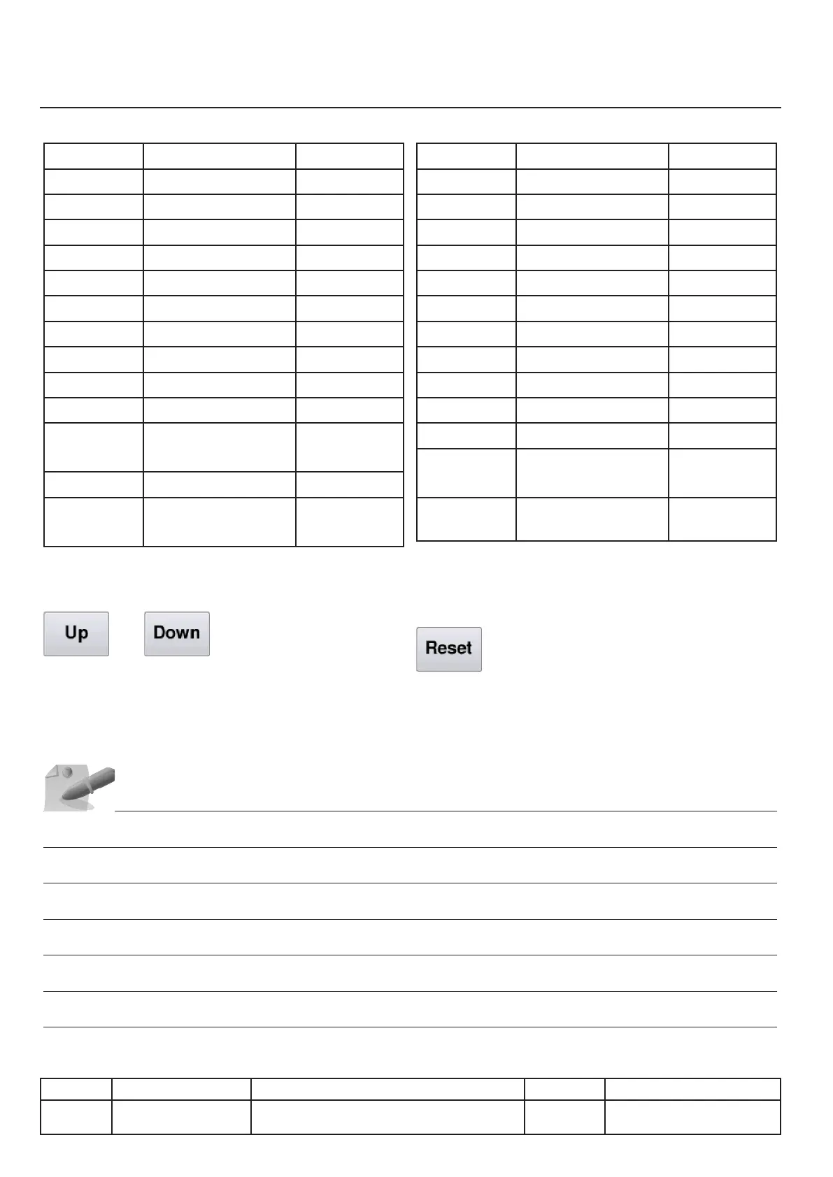
Probes on the left side
Probe Use Unit
B1
Pan temperature All
B4
Temperature R1 All
B5
Temperature R2 All
B6
Temperature R3 All
B7
Temperature R4 112L, 211, 311
B8
Temperature R5 112L, 211, 311
B9
Temperature R6 112L, 211, 311
B10
Temperature R7 211, 311
B11
Temperature R8 211, 311
B12.1
Left core probe tip All
B12.2 -
B12.5
Median point of left
core probe
All
B12.6
Left core probe handle All
Temp.
PCB
Main Board A2 All
Buttons
●Selection of a row in the table
Probes on the right
Probe Use Unit
B2
Pan temperature 112, 112T
B7
Temperature R4 211, 311
B8
Temperature R5 211, 311
B9
Temperature R6 211, 311
B10
Temperature R7 112L
B11
Temperature R8 112L
B14
Temperature R9 112L
B15
Temperature R10 112L
B16
Temperature R11 112L
B17
Temperature R12 112L
B13.1
Right core probe tip 112, 112T
B13.2 -
B13.5
Median point of right
core probe
112, 112T
B13.6
Right core probe
handle
112, 112T
●Initialisation of the maximum value set to the
current value
IV.06
v03 • July-2016 • Hen
Service Mode Module
Line Units Serial number (starting from) Sw Revision
VCCM
VCCWE
All ExxXH1009xxxxxxx 01-00-08