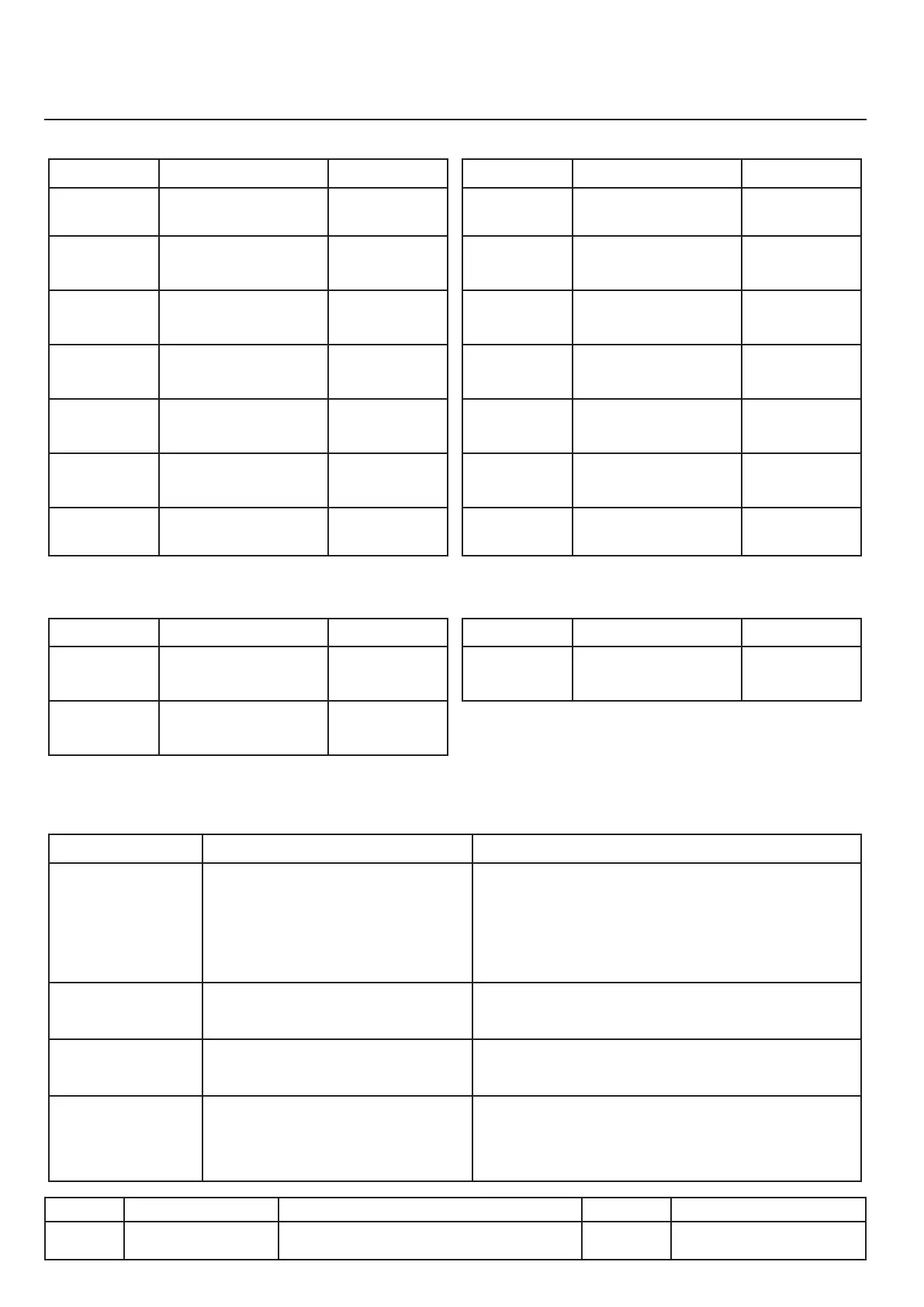
Description of the Service Mode
Diagnosis, sensors
Contacts on the left side
Probe Use Unit
Cover up
Limit switch S10, cover
up
112, 112T; 112L
Cover
down
Limit switch S11, cover
down
112P
Cover
unlocked
Limit switch S6, cover
unlocked
112P, 211P,
311P
Cover
locked
Limit switch S7, cover
locked
112P, 211P,
311P
Pan
valve
Microswitch S8,
position pan valve
All
Pan
down
Limit switch S25,
pan down
112T
Pan up
Limit switch S27,
pan up
112T
Left potentiometer
Probe Use Unit
Angle of
pan
Potentiometer PT1 112, 112T,
112L, 211, 311
Cover
angle
Potentiometer PT2 211, 311
Contacts right side
Probe Use Unit
Cover up
Limit switch S12, cover
up
112, 112T, 112L
Cover
down
Limit switch S13, cover
down
112P
Cover
unlocked
Limit switch S18, cover
unlocked
112P,
Cover
locked
Limit switch S19, cover
locked
112P
Pan
valve
Microswitch S20, posi-
tion pan valve
112, 112T, 112L
Pan
down
Limit switch S26,
pan down
112T
Pan up
Limit switch S28,
pan up
112T
Right potentiometer
Probe Use Unit
Angle of
pan
Potentiometer PT2 112, 112T, 112L
Columns displayed
Column Explanation Details
Code
Name of the sensor concerned ●S for microswitch, limit switch
●Y for solenoid valves
●PT for potentiometers
●P for pressure sensors
Status
Sensor status ●0 for inactive
●1 for active
Angle
Angular value calculated based on
the digital value (gross value)
●Value calculated in relation to the last point
of reference
Gross value
Or digital value. This is the gross
value of the potentiometer
(without angle conversion)
IV.08
v03 • July-2016 • Hen
Service Mode Module
Line Units Serial number (starting from) Sw Revision
VCCM
VCCWE
All ExxXH1009xxxxxxx 01-00-08