EasyManua.ls Logo

VAT 650 Series User Manual

VAT 650 Series
94 pages
To Next Page IconTo Next Page
Page #1 background imageLoading...
Page #1 background image
Installation, Operating & Maintenance Instructions
Series 650 DN 100-250 (I.D. 4“ - 10”), CC-Link
VAT Vakuumventile AG, CH-9469 Haag, Switzerland
Tel +41 81 771 61 61 Fax +41 81 771 48 30 CH@vatvalve.com www.vatvalve.com
280672EB
2010-12-15
1/94
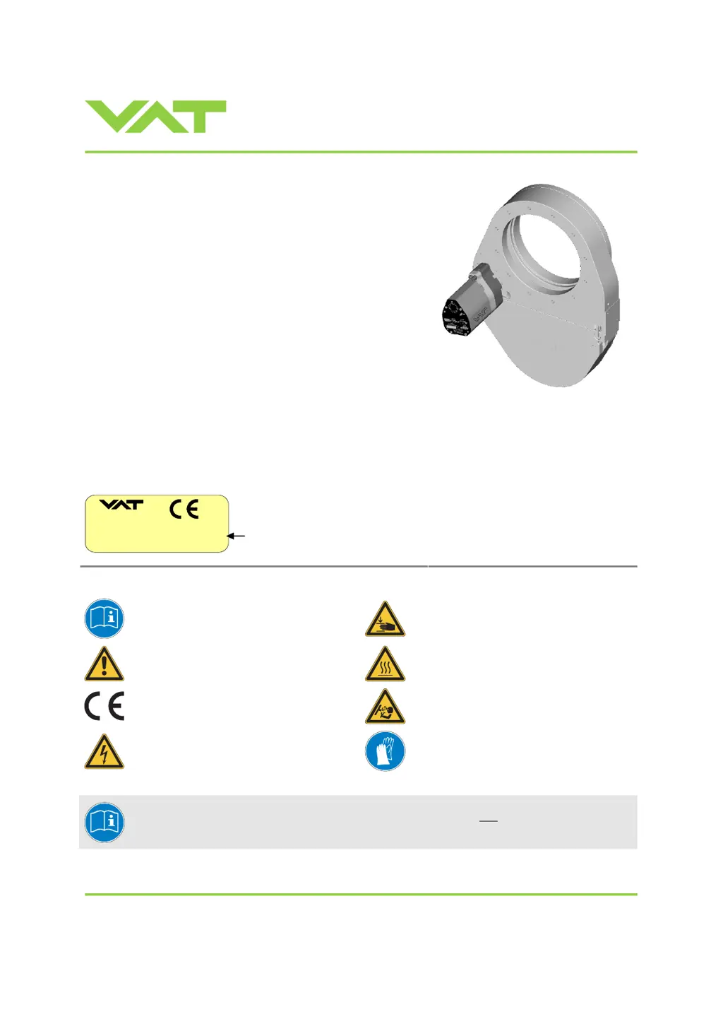
Pendulum control & isolation valve
with CC-Link interface
with valve cluster functionality
This manual is valid for the valve ordering number(s):
650 . . - . . TL - . . . . (Master / 1 sensor input)
650 . . - . . TN - . . . . (Master / 2 sensor inputs)
650 . . - . . VL - . . . . (Master / 1 sensor input / ±15V SPS)
650 . . - . . VN - . . . . (Master / 2 sensor inputs / ±15V SPS)
650 . . - . . UL - . . . . (Master / 1 sensor input / PFO)
650 . . - . . UN - . . . . (Master / 2 sensor inputs / PFO)
650 . . - . . WL - . . . . (Master / 1 sensor input / ±15V SPS / PFO)
650 . . - . . WN - . . . . (Master / 2 sensor inputs / ±15V SPS / PFO)
650 . . - . . GS - . . . . (Slave)
650 . . - . . HS - . . . . (Slave / PFO)
SPS = Sensor Power Supply PFO = Power Failure Option
Master and Slave are configured with firmware 650C.1E.12
The fabrication number is indicated on each product as per the label
below (or similar):
made in Switzerland
Fabrication No.:
patented
. .
650
. .
. . . . / . . . .
A
. . . . . .
Fabrication number
sample picture
Explanation of symbols:
Read declaration carefully before you start any other
action!
Keep body parts and objects away from the valve
opening!
Attention!
Hot surfaces; do not touch!
Product is in conformity with EC guidelines,
if applicable!
Loaded springs and/or air cushions are potential
hazards!
Disconnect electrical power and compressed air
lines. Do not touch parts under voltage!
Wear gloves!
Read these «Installation, Operating & Maintenance Instructions» and the enclosed «General
Safety Instructions» carefully before you start any other action!

Table of Contents

Questions and Answers:

VAT 650 Series Specifications

General IconGeneral
Supply voltage24 VDC
Digital inputs8
Digital outputs8
Analog inputs4
Analog outputs2
MountingDIN rail
Output Voltage24 VDC
Current Rating2 A
Weight0.5 kg
Communication interfaceRS-485
ProtocolsModbus RTU
ProtectionShort-circuit, overload

Summary

1 Use of product

1.1 Technical Data

Provides detailed specifications for the control and actuating unit.

2 Installation

2.1 Unpacking and System Integration

Covers unpacking, system installation, and connector panel overview.

2.3 Mechanical Mounting and Torque

Details tightening torque, admissible forces, and mounting requirements.

2.5 Sensor Connection and 2.6 Electrical Connections

Covers sensor connection requirements and electrical wiring details.

2.6.7 CC-Link Interface and 2.6.10 Valve Cluster

Covers CC-Link cable installation, connectors, network, and valve cluster connection.

3 Operation

3.1 Introduction and Operational Modes

Overview of valve cluster, operational modes, and basic behaviors.

3.3 System Behavior and 3.5 Display Information

Describes valve behavior during power up/failure and display information.

3.6 Setup Procedures and Configuration

Essential steps for configuring the valve cluster for operation.

3.6.1 Cluster Addressing and CC-Link Setup

Configures unique cluster addresses and CC-Link parameters.

3.6.3 Valve and Sensor Configuration

Adapting valve configuration and setting up ZERO/LEARN.

3.9 Control Modes and 3.10 Pressure Control

Managing position control, pressure control, and performance tuning.

3.10.1 Tuning Control Performance

Detailed adjustments for gain factor, sensor delay, setpoint ramp, and valve speed.

3.11 CC-Link Interface Communication

Details on CC-Link schematics, handshaking, buffers, and communication timing.

3.11.7 & 3.11.8 Master PLC Data Buffers

Overview and details of OUTPUT and INPUT buffers for PLC communication.

4 Trouble shooting

4.1 Failure Diagnosis and CC-Link Warnings

Identifies common failures, troubleshooting steps, and CC-Link warnings.

5 Maintenance & repairs

5.1 Preventive Maintenance Procedures

Recommended maintenance schedules for seals and valve cleaning.

5.2 Option Board Management

Information on option boards, battery life, and replacement procedures.

6 Drawing

Valve Component Diagram

A labelled diagram showing the main components of the valve.

7 Spare parts

7.1 Control Unit and 7.2 Valve Unit Spares

Lists spare parts for control and valve units, including seals and boards.

7.3 Accessories and Mounting Parts

Details available accessories like power supplies, software, and centering rings.

8 Warranty

Product Warranty Information

Outlines the warranty terms and conditions for VAT products.

Related product manuals