Manual Micro Dispensing Systems MDS 3010A-FA and MDS 3020A-FA
VTK-VS-BA-002 Revision B 26
4
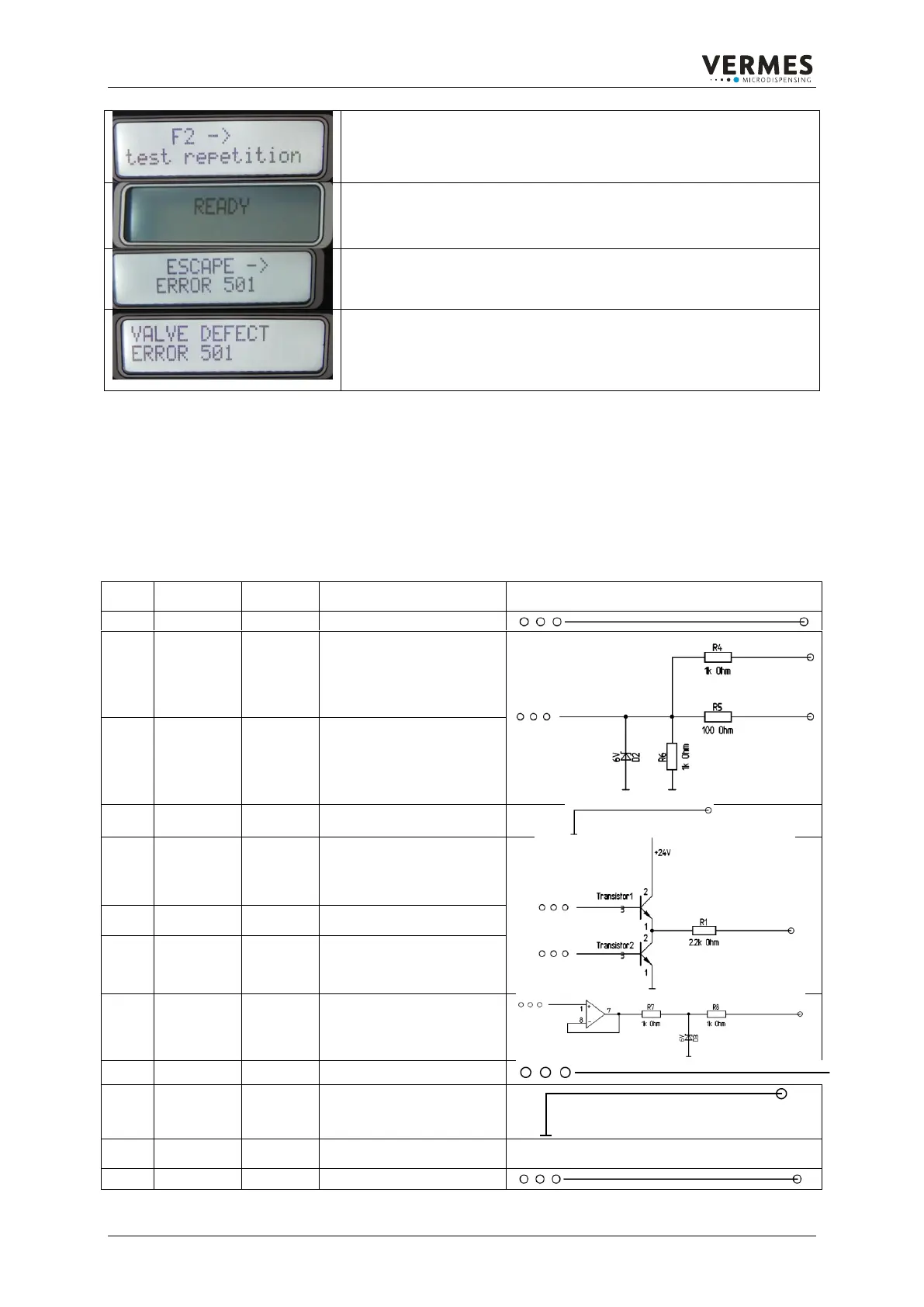
While the test is running, the message “F2 -> test repetition” is displayed.
If the test was successful, you can start dispensing (see 5). If it was not
successful, the display jumps back to the message from 3.
5
The test was successful. The regular „Ready“ message appears. You can
start with your application.
6
You have pressed the [esc]-key as option (in 3). For a few seconds the
message “ESCAPE -> ERROR 501” appears.
7
Finally the message “VALVE DEFECT ERROR 501” appears and stays
on. All the function keys of the MDC are locked. Switch off the MDC.
Remove the valve. It has to be send back to VERMES Microdispensing for
maintenance.
Table 10. Handling Error 501 Valve Defect
7.5.5. PLC-interface: Sub-D, 15-pin
The PLC interface is a bit-oriented interface without special syntax.
It offers access to:
status bits
voltage and current values
set trigger input which causes dispensing impulses or impulse packages (burst)
Trigger voltage input,
rising edge
0 ... +5 V „Valve closed“
+12 V ... +30 V „Valve
opened“
positive edge triggered
Trigger voltage input,
rising edge
0 ... +0.8 V „Valve closed“
+3,5 V ... +5 V „Valve
opened“
Positive edge triggered
Heating ok function signal
Not in use for FA
Nozzle insert adjusted OK
“green light”
Main voltage indicator OK
“hardware power on”
tappet stroke – sensor
signal
analog output “U needle”
 Loading...