Manual Micro Dispensing Systems MDS 3010A-FA and MDS 3020A-FA
VTK-VS-BA-002 Revision B 28
External Mode
per PLC-signal and external-control-mode: Open Time “external”:
the parameters Rising, Falling, Delay, Needle Lift und Number of Pulses using the
adjusted values.
Open Time until the PLC-signal is set on logic 1. The valve gets closed when logic 0 is
set. Next impulse will be processed.
Infinite Mode
per PLC-signal: Number of Pulses “0”/per keypad: Number of Pulses “infinite”.
predefined duration of the burst
Rising, Open Time, Falling, Needle Lift are using the adjusted values.
If the PLC signal is set to logic 1, the valve is starting the burst and continues until the
signal is set to logic 0.
7.7. Delay times
7.7.1. PLC Trigger Delay
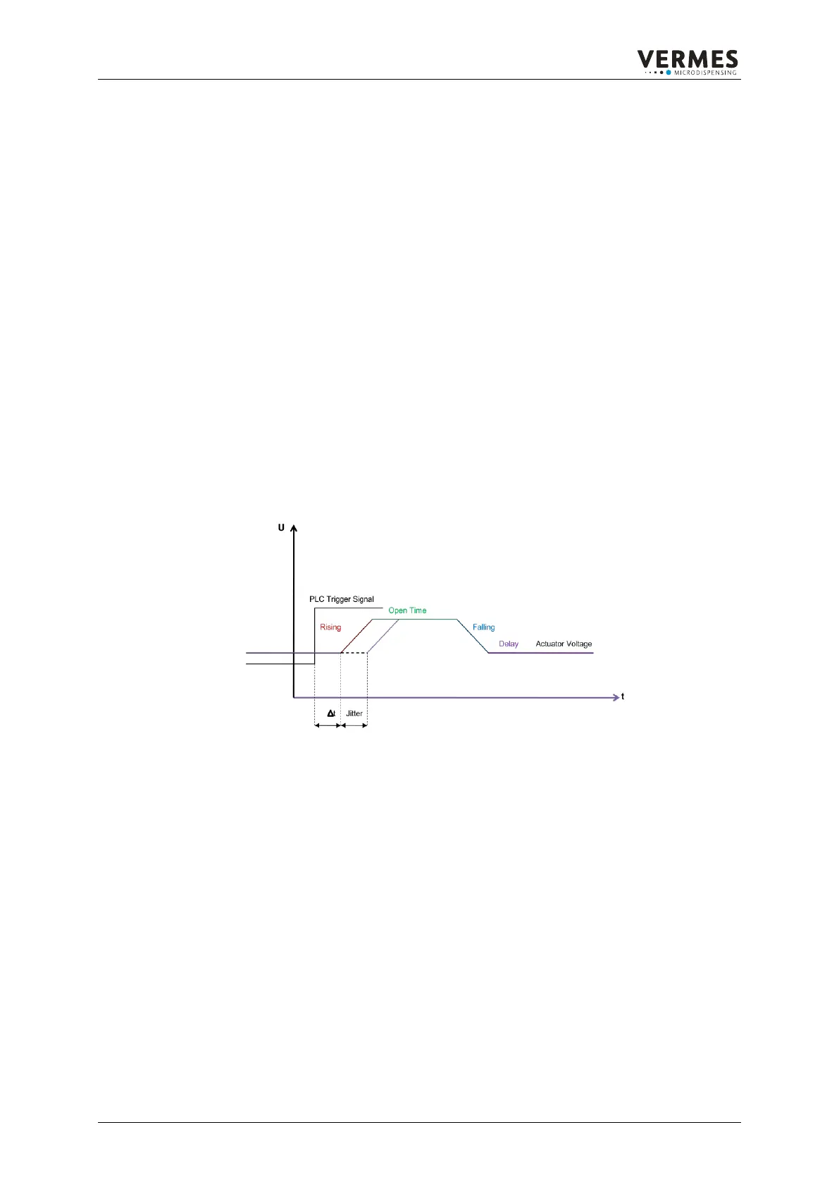
The following charts are showing the delay times for the different control options:
Normal Mode/External Mode/Infinite Mode
t = 131µs. Jitter = 3µs
Figure 14: The Delay between the PLC Trigger and the actuator voltage
The charts show the delay between the PLC Trigger and the actuator voltage. It is measuring
from the rising shoulder of the trigger impulse to the beginning of the rising shoulder of the
actuator voltage under signification of the Jitter.
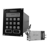
8. Connection/Mounting
8.1. Assembling the valve
The Micro Dispensing Valve should be mounted on a smooth and even vertical space by means of
the two tap holes (M4) at the narrow side. The distance between the bore holes is 45 mm. The
screwing depth is approximately 4 mm. All parts in contact with the Micro Dispensing Valve
(screws, fixing plates etc.) should be made of stainless steel, non-ferrous metals or galvanized
steel. Contact with non-refined ordinary steel may cause so called “external rust”.