Manual Micro Dispensing Systems MDS 3010A-FA and MDS 3020A-FA
VTK-VS-BA-002 Revision B 29
Figure 15: Image of the bore holes of the valve MDV
8.2. Assembling the control unit
The control unit MDC 3090A-FA is designed as an insert for a 19” plug-in module. It may be fixed
in a place, sufficiently ventilated as well as easy to reach from the rear and the front side in a 19”
rack with 4 front side screws. The connecting cables have to be thoroughly guided. All connectors
must be fixed tight. A possible interchanging of plugs and sockets is prevented by corresponding
coding.
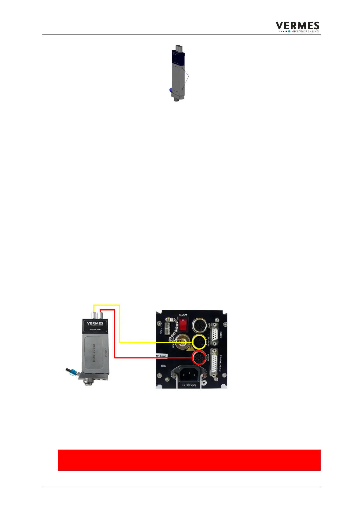
8.3. Electrical connections
The connection of the Micro Dispensing Valve is done via the two 4-pin sockets on the sensor
electronics module. The sockets are protected against mix-up by a corresponding coding. The red
dots on the socket and the plug shall point to each other when connecting. The cable marked with
a red tension relief supplies the power for the piezo stack from 0 V to 200 V. Via the second cable
(yellow tension relief) the data of the tappet sensor integrated in the MDV 3xxx is transferred.
Disconnection is done by pulling the riffled bush axially backwards.
Step 1: Make sure line cord is disconnected from control unit
Step 2: Connect both control cables (red and yellow tension relief) to the Micro Dispensing Valve.
Pay attention to the coding of the cable and females.
Step 3: Connect both control cables to the back side of control unit (screw tightly!)
Step 4: Connect the power cable to the back side of control unit. Before connecting pay attention
to line switch „0“-position, i.e. when the inscription „0“ is visible (top view).
Figure 16: Connection scheme of valve and control unit
8.4. Fluid box connections
For the connection of the fluids to be dispensed, there are several clutch systems for tube or pipe
obtainable. Also available are cartridge connectors in different sizes and types. These VERMES
Microdispensing standard connections stand for a minimum of dead space capacity.
Attention!!!
Be sure that all junctions and connectors are mounted according to regulations and all used
components are designed for pressure being applied.
2x Gewinde M4
Einschraubtiefe jeweils 4 mm
Mittelpunktabstand 45 mm
2x thread M4
screw-in depth 4mm
Centre distance 45 mm



 To Next Page