To connect the cable:
NOTE: Input and output cables must be run in separate conduit before cable connection.
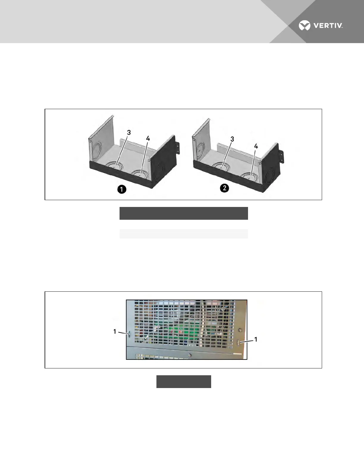
1. Remove the knockouts at the junction box, see Figure 3.22 below, and pull the cables through
them, leaving some slack for installation.
Figure 3.22 Knockouts in Units without Transformer
ITEM DESCRIPTION ITEM DESCRIPTION
1 16-bay, no transformer 3 Output-cable knockout
2 10-bay, no transformer 4 Input-cable knockout
2. Connect the cables to the corresponding terminal of the power input and output terminals.
3. Using a 13-mm (1/2-in.) torque wrench, tighten the screws to 4.52Nm (40in-lb).
4. Respectively, secure the conduit of the input/output cables through the cable bridges on the
rear panel of the UPS, see Figure 3.23 below.
Figure 3.23 Secure cables on cable bridges
ITEM DESCRIPTION
1 Cable bridge
The connection methods for single-phase and the 3-phase input modes are shown in 3.7.3 on page41
and 3.7.3 on page41, respectively. Installation of the factory-provided copper bar is essential in the
single-phase input mode. The copper busbar is in the accessory bag included with the UPS.
Vertiv | Liebert® APS™ Installer/User Guide | 43