Vertiv | Liebert CRV+ | User Manual 18
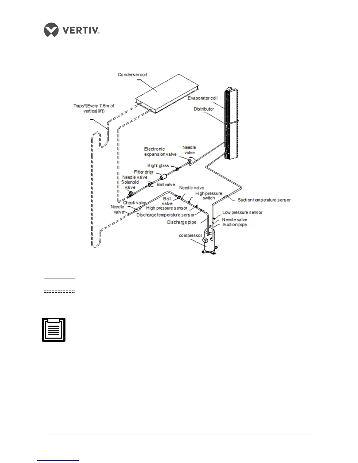
2.3.1 System arrangement during installation
The general arrangement of the CRV+ air cooled AC unit is depicted in Figure 2-6.
Figure 2-6 System Arrangement
: Factory piping.
: Field piping (by technical personnel).
The following points should be considered before checking out the overall layout diagram:
The
single system is used as an example to describe the entire system.
Vertiv staff and qualified professionals lay out the piping in the laboratory.
Piping is done by technicians.
Components (marked with *) are not supplied by Vertiv Co. but are recommended for
proper circuit operation and maintenance.
Additional components (marked with +) are required when the equivalent length exceeds
30m.