Vertiv | Liebert CRV+ | User Manual 20
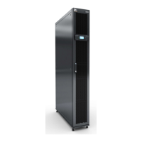
Figure 2-8 depicts the schematic diagram of system installation when the condenser is installed at a
lower level than the compressor.
Figure 2-8 The Condenser is lower than the Compressor during installation
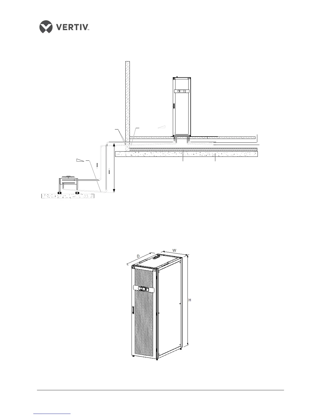
2.3.3 Product Dimensions
The dimensions and weight of the indoor unit are displayed in Figure 2-9 and in the table within Listing
2.2.
Figure 2-9 Dimensions of an indoor unit
Heat insulation floor
Floor
Sealed
Raised floor
Humidifier
water in
Condensed
water out
Indoor unit
Slope liquid
Min. 8m
Slope
discharge
Outdoor unit