Vertiv | Liebert CRV+ | User Manual 19
2.3.2 System Installation Mode
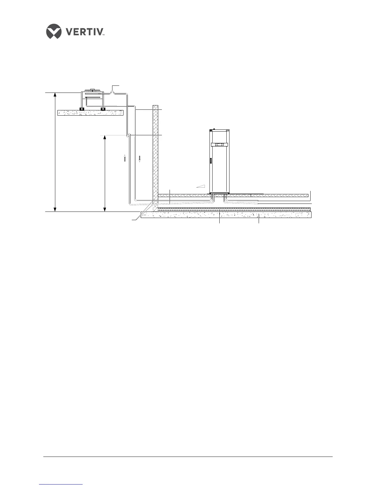
The system installation schematic diagram explains the process of installation for the Condenser:
Figure 2-7 Condenser is placed higher than the Compressors during installation
In Figure 2-7, the condenser is installed higher than the compressor. Therefore, an inverted back bend is
fitted to the discharge line and the liquid line of the condenser. The modification is essential as it helps
prevent the liquid refrigerant from flowing back once the condenser stops. The top end of the inverted
backbend must be installed higher than the ultimate level of the copper pipe of the condenser.
However, if the condenser is installed lower than the compressor, then there is no modification required
as it fits the bill perfectly.
Back bend (must be higher than the
highest copper pipe of the condenser)
Heat insulation floor Floor
Sealed
Raised floor
Humidifier
water in
Condensed
water
Indoor unit
Liquid line (avoid exposure to direct sunlight)
Trap
Slope discharge
Max. 7.5m
Max. 30m
Outdoor unit