Vertiv | Liebert® CRV4 | User Manual 15
Mechanical Installation
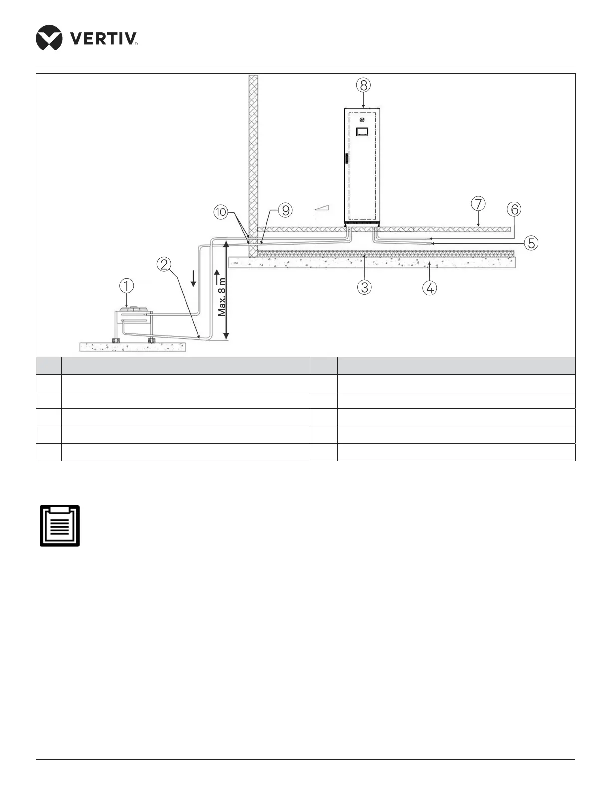
No. Description No. Description
1 Outdoor unit 6 Humidier water in
2 Slope liquid 7 Raised oor
3 Heat insulation floor 8 Indoor unit
4 Floor 9 Slope discharge
5 Condensed water out 10 Sealed
Figure 3-3 The Outdoor Unit is Lower than the Compressor during Installation
• In Figure 3-2, the outdoor unit is installed higher than the compressor. Therefore, an inverted backbend is
tted to the discharge line and the liquid line of the outdoor unit. The modication is essential as it helps
prevent the liquid refrigerant from owing back once the outdoor unit (condenser) stops.
• The top end of the inverted backbend must be installed higher than the ultimate level of the copper piping
of the outdoor unit. However, if the outdoor unit is installed lower then the compressor no modication is
required.
 Loading...


