Vertiv | Liebert® CRV4 | User Manual 41
Electrical Installation
Table 4-1 MCB Current for the Models
Model MCB Current [ampere (A)]
CR025 NDM1-63C40/3 40
CR035 NDM1-63C50/3 50
CR045 NDM1-63C63/3 63
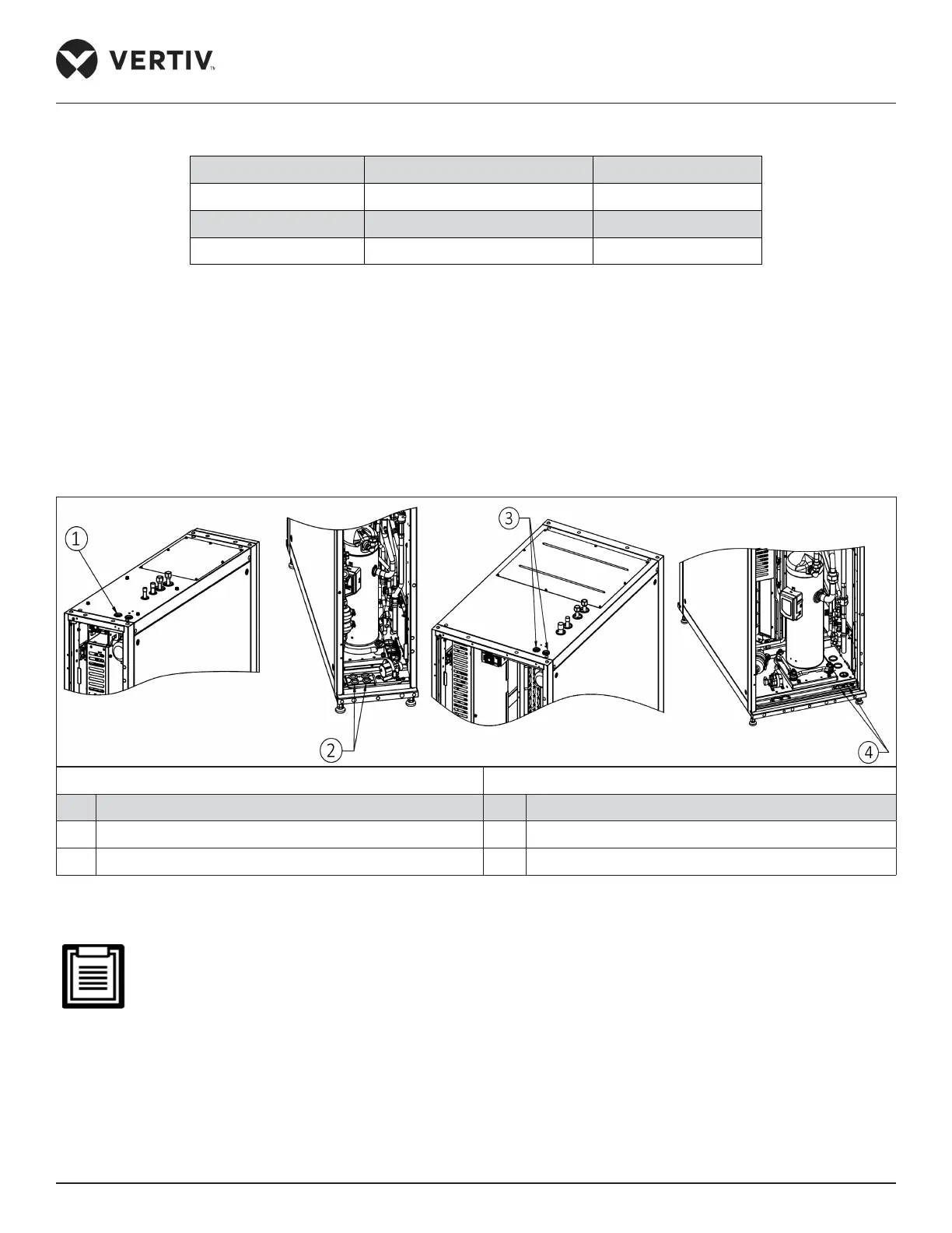
4.2.2. Connecting the Power Cable of the Indoor unit
The specic location of the power port of the indoor unit is shown in Figure 4-1. Connect the supply terminals
L1-L3, N, and PE to their respective counterparts of the external power supply respectively. Fix the input cables
to the cable clamp, located on the inner side panel of the unit. The top cable entry and bottom cable entry
holes are shown in Figure 4-2.
For the cable specications, refer to the full-load current (FLA) described in the Table 4-2.
CR025 CR035 & 045
No. Description No. Description
1 Top cable inlet holes 3 Top cable inlet holes
2 Bottom cable inlet holes 4 Bottom cable inlet holes
Figure 4-2 Top and Bottom Cable Entry Holes
The cable sizes must strictly meet and adhere to the local cabling regulations and protocols as it supersedes
every type of connection.
 Loading...


