Vertiv | Liebert® CRV4 | User Manual 27
Mechanical Installation
In some cases, the process needs to be in compliance with the local laws and regulations resulting in the
installation of some other supporting components, for more details consult Vertiv representative.
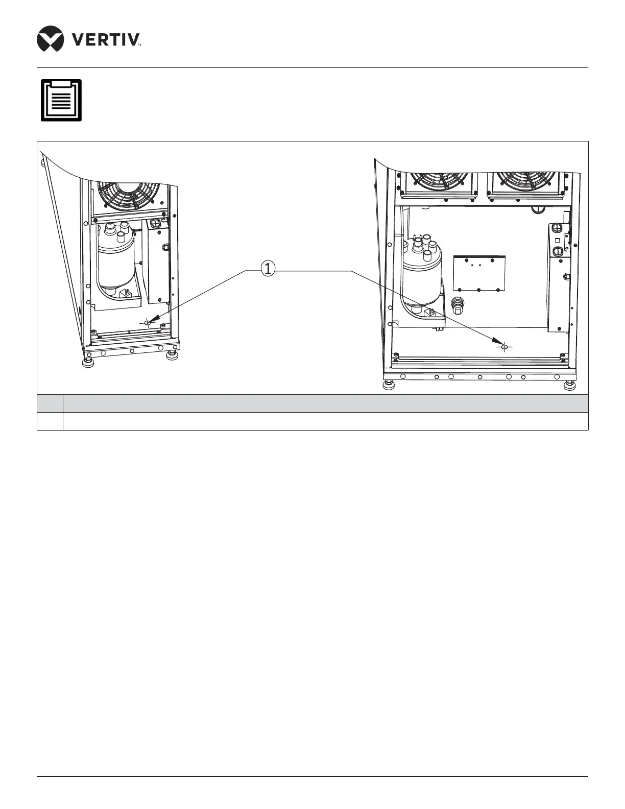
No. Description
1 Humidier inlet hole
Figure 3-15 Electrode Humidier Water Inlet Pipe Connection from Bottom
3.3.4. Connection of the Copper Piping between the Indoor and Outdoor Units
• The indoor and outdoor units are connected through brazed copper piping. Select the appropriate
dimension (pipe diameter) of piping connecting the indoor and the outdoor unit. Considering the eect
of the diameter of copper piping on the pressure drop of the system, the pipe dimensions of the indoor
and outdoor units should be determined according to the specications in Table 3-2 or contact Vertiv
representative.
• The unit has refrigerating pipe connectors and labels on its top and bottom as shown in Figure 3-16 and
Figure 3-17. Notes and instruction labels are pasted onto the discharge and liquid piping. Therefore, ensure
that the piping must be wrapped with a wet cloth before brazing to protect the labels from burning.
• Connect the discharge pipe and liquid pipe of the indoor unit according to the instructions on the labels.
• Horizontal sections of the discharge pipe should be sloped down from the compressor with a slope of at
least 1:200 (5 mm down for each 1 m run). The discharge pipes should be insulated where they are routed in
the conditioned space (including under a raised oor).
 Loading...


