Vertiv | Liebert® CRV4 | User Manual 29
Mechanical Installation
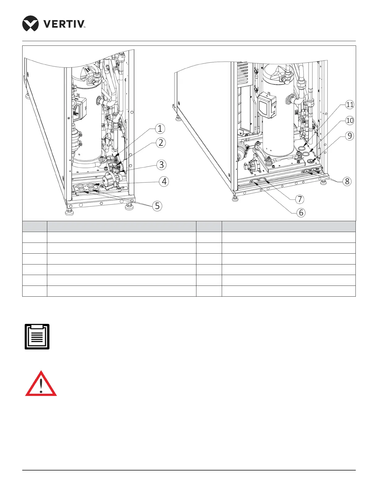
No. Description No. Description
1 Weight-drain water hole 7 Weight-drain water hole
2
Liquid pipe inlet hole of evaporator 8 Bottom cable inlet hole
3 Exhaust air hole of compressor 9 Exhaust air hole of compressor
4 Drain water hole of pump 10
Liquid pipe inlet hole of evaporator
5 Bottom cable inlet hole 11 Water pipe inlet hole of wet lm humidier
6 Drain water hole of pump
Figure 3-17 Bottom Plate Piping Connection
For bottom piping: before brazing the compressor discharge pipe and liquid pipe, follow the instruction
labeled on the copper pipe; cut the copper pipe using a cutter (a little bit of the compressor lubricant oil may
leak); however, do not braze the copper cap on the seal directly as it may result in heating of the oil following
which it may catch re.
The exposure time of system piping must not exceed 15min. Longer exposure will lead to the compressor
lubricant oil being aected by moisture, which can aect the life of the key components and the system
operation stability.
 Loading...


