Vertiv | Liebert® CRV4 | User Manual 55
Micro-Controller (Color Screen)
6.3.2. Main Interface Control Mode
The main interface is divided into temperature control mode, humidity control mode, temperature value
in current control mode, theoretical supply air humidity value, and three read-only status of temperature /
humidity setting value.
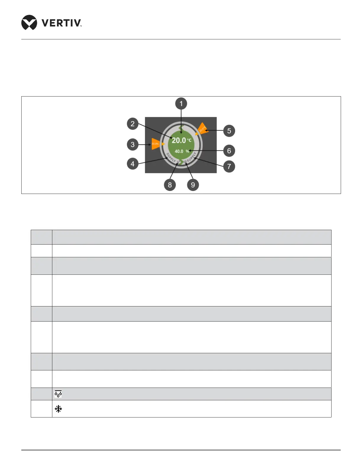
Figure 6-3 Control Mode Diagram
Table 6-3 Description of Control Mode Diagram
No. Description
1 The colors in the circle are red, gray and green (depending on the status of the unit).
2
The measured supply air temperature value changes with the change of the compressor’s current control
mode.
3
The humidity setting value changes and rotates clockwise between 30° - 150° polar coordinate angles
according to the range of humidity setting value. When the humidity setting is at minimum value, the
value is 30° in the polar coordinate; when the humidity setting value is at maximum value, and the
humidity setting value is 150° in the polar coordinate.
4 Humidity control is the air supply humidity control by default, showing “supply”.
5
The temperature setting value changes and rotates clockwise between 30° - 150° polar coordinate angles
according to the range of temperature setting value. When the temperature setting is at minimum value,
the value is 30° degrees in the polar coordinate; when the temperature setting value is at maximum value,
and the temperature setting value is 150° degrees in the polar coordinate.
6 Theoretical air supply humidity value.
7 The current control mode of compressor is air supply humidity control by default, showing “supply”.
8
means humidity.
9
means temperature.
 Loading...


