030624.13 57
vetus® Electronic engine remote control
Follow the steps from 1 to 8 as reported here below:
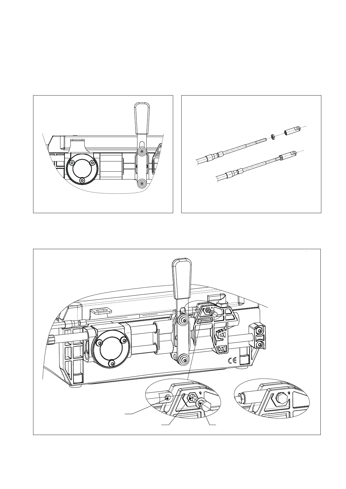
1. Verify that the actuator’s gear lever is in neutral position, as depicted in the picture here below (1). The lever should
be vertical, otherwise enter into the JOG MODE and move the actuator’s lever to central position. For this operation
follow steps from 1 to 7 of section 12.1. The neutral position is parameter “0F”.
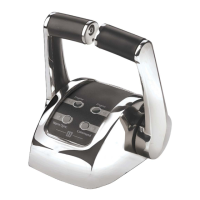
2. Verify that the position of the gearbox lever is in neutral on the gearbox side as described previously. The push-pull
cable must be at its half stroke also on the actuator’s side. Then screw the eyelet (h) onto the cable’s rod (2).
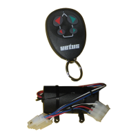
3. Position the push-pull cable with the hole on the eyelet (H1) aligned with the hole of the plastic slider (H2). Insert the
screw (+ elastic washer) and fasten it.
H1
H2 a
1.
3.
2.