VI.BE.MAC.S.p.A. 3022LV
Page 25
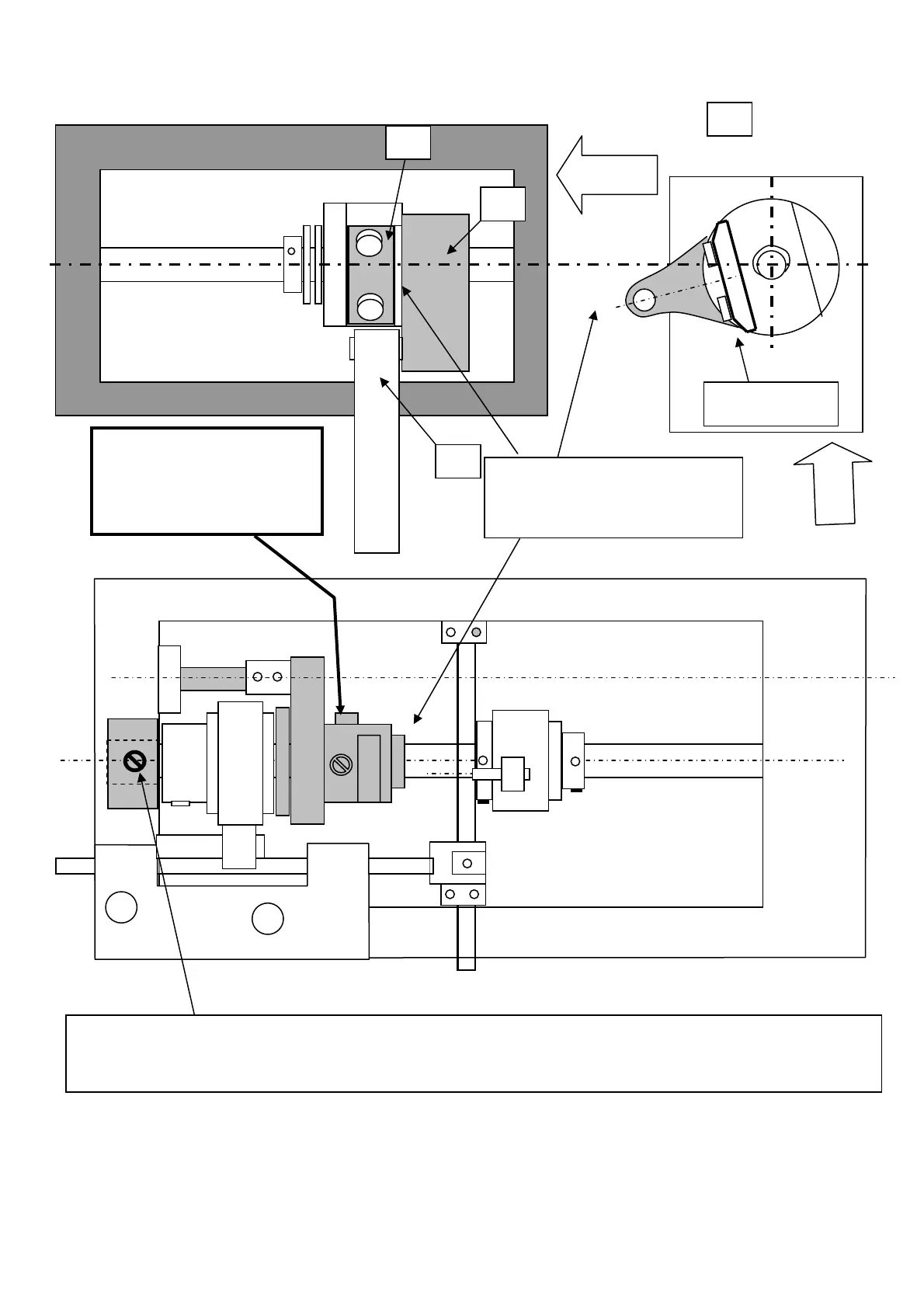
15.9 CLAMP MOVEMENT CAM
Set the flat surface located on
the Lower Eccentric Pinion like
the Upper Eccentric Pinion,
when the Upper one has it in
vertical position the Lower one
must be in the same must be
1
2
3
Eccentric Pinion
Flat surface
Eccentric Pinion Flat surface 90°
with respect to the connecting
rod axis, when the Needle Bar is set
on the Bottom Point
Lateral view
Front
view
1
CLAMP ELLIPSE ADJUSTMENT
With the needle bar at bottom dead centre, turn the hand wheel and raise the needle bar by 1.5 mm. The second screw in
direction of rotation must line up with the vertical service hole.
NB. THIS ADJUSTMENT CAN ONLY BE MADE BY REMOVING THE PLATE SUPPORTING THE CLAMP.
 Loading...