VIDEONICS DIGITAL VIDEO MIXER PAGE 13
It is possible to work with an output monitor and no PREVIEW monitor.
This is not a recommended setup because it requires you to work “blind,”
without the benefit of the on-screen controls or input previews.
More Than Two Monitors
You can add a monitor for each input as well. Input monitors are used
when you need a constant full screen, high-quality view of the inputs. Con-
necting the input monitors is explained later in this chapter.
IN and OUT Markings
IN
OUT
IN
OUT
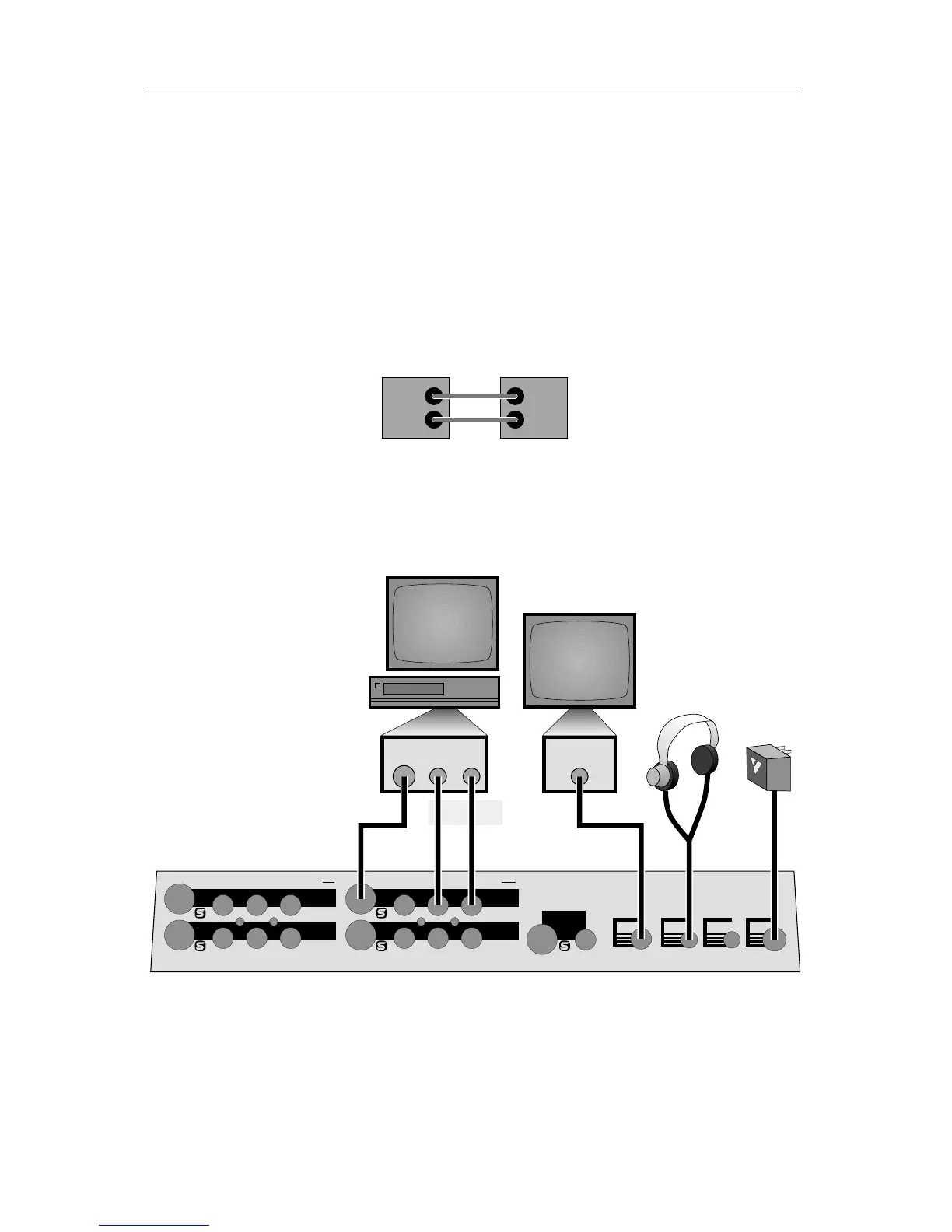
Hint: Always connect the OUT jack of one device to the IN jack
of the next. Never connect two OUTs together.
Connecting Power, Outputs, Monitors
PREVIEW
OUT
POWER
HEAD
PHONE
IN 4
IN 1
IN 2
OUT
IN 3
CONTROL
(
GPI
)
POWER
CONTROL HEADPHONE PREVIEW V — IN 4 — S RLV S RLV S
IN 3
OUT
IN 2
IN 1
V
LRV
LRVLRV
LRV
A
BCD EF
VIDEO
IN
AUDIO
IN
VIDEO
IN
Example Power and Output Connections
■ Connect the power supply (F) to the POWER input and plug it into a
working power outlet. Be sure to use the power supply that came with the
Mixer. Others, including the ones supplied with other Videonics products, may
damage the unit and void the warranty.
Move the POWER switch on the front panel to the ON (up) position and
the light above the switch will come on.