VIDEONICS DIGITAL VIDEO MIXER PAGE 15
• Others require that you choose a special channel (like 99 or A1).
• Still others switch automatically when you plug the cable into the VIDEO
IN jack.
■ Check the connections.
Turn the MX-1, VCR, and television on and press DEMO. You should see a
series of images with various transitions between them. Press DEMO
again to stop the demo.
■ Connect the PREVIEW monitor.
Connect the MX-1’s PREVIEW OUT to the VIDEO IN jack of the PREVIEW
monitor (D) using a composite (RCA-style) cable. (If the monitor only has
an RF (cable/antenna) jack, you will need a spare VCR or an RF modulator
to convert the RCA-style output to RF.)
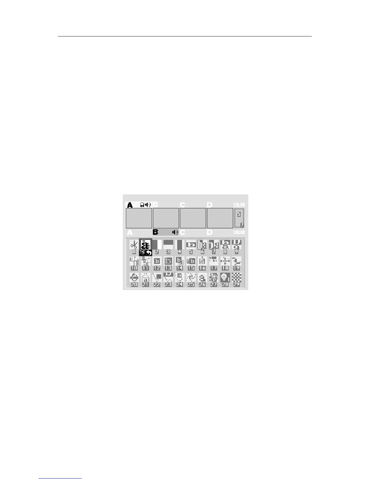
■ Test the PREVIEW connection.
Turn the PREVIEW monitor on. You should see the PREVIEW screen:
■ Connect headphones.
If you wish to use headphones, connect them to the HEADPHONE jack
(E). The headphone jack accepts standard stereo headphones with a min-
iature plug, but the output is monaural (a mix of right and left channels),
not stereo.
■ CONTROL (GPI).
The CONTROL (GPI) input allows the Mixer to be triggered by GPI-
equipped edit controllers. It is described in Chapter 19, “Editing and Other
Applications.”
Connecting Sources
Video sources include camcorders, VCRs, laserdisc players, cameras, sat-
ellite tuners, broadcast tuners/receivers, video-equipped computers, etc. They
may have S-video (Y/C) or composite (RCA-style) output jacks. RF sources
(cable TV, antenna, “channel 3/4,” or other modulated sources) must be