PAGE 16 VIDEONICS DIGITAL VIDEO MIXER
converted to S-video or RCA-style format video using a tuner, television,
VCR, etc.
You can mix input types, using S connections for some sources and RCA
for others. When you have both, S is preferred.
■ Connect each video source’s VIDEO OUT jack to the appropriate video IN
jack on the Mixer. Be sure to note which source is connected to which input
(IN 1 through IN 4).
IN 4
IN 1
IN 2
OUT
IN 3
V — IN 4 — S RLV S RLV S
IN 3
OUT
IN 2
IN 1
V
LRV
LRVLRV
LRV
K
J
G
HM
LN
I
VIDEO
OUT
AUDIO
OUT
VIDEO
OUT
AUDIO
OUT
VIDEO
OUT
AUDIO
OUT
VIDEO
OUT
AUDIO
OUT
VCR 1
VCR 2 VCR 3
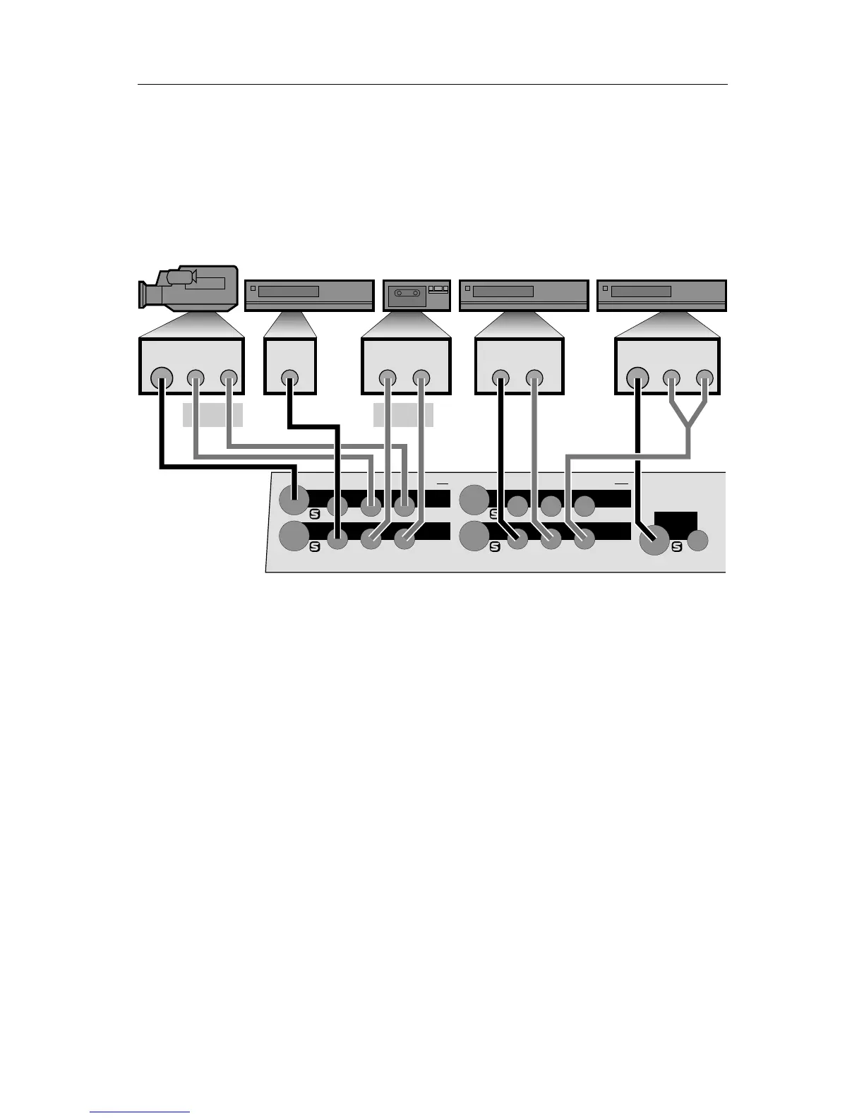
Example Input Connections
In the example above, a camcorder is connected to IN 1 (G) and VCRs are
connected to each of the other three inputs (I, K, L).
The camcorder and the last VCR are connected to S-video inputs (G and
L). The others (I and K) are connected to composite (RCA-style) jacks.
■ Disable processing circuits.
Some VCRs have circuitry that is intended to improve the apparent sharp-
ness of their outputs. These circuits often boost the signal past standard
limits and can interfere with the MX-1’s TBC (time base corrector). We
recommend you turn such options off.
The most common processing control is the EDIT switch. This switch
should be set to the ON position (which disables processing). Another
common control is SHARPNESS which should be set to zero or off.
■ Connect the audio inputs.
Connect each audio source’s AUDIO OUT jack to the appropriate audio
IN jack on the Mixer. Audio can come from audio devices, such as tape
and CD players, as well as from VCRs and camcorders.
Usually, the sound from each VCR or camcorder will be connected along-
side the video connection, the way the camcorder is connected in the