15
Terminals:
2
Speech output.
13Vac power input for the LEDs.
3
+8Vdc power input.
1
Speech input.
4
Speech ground.
Ground (0V) for 13Vac.
P
2
Call button user Nr.2.
P
1
Call button user Nr.1.
C
Push buttons common.
Morsettiera:
2 Uscita fonia.
Ingresso 13Vac per LED d’illuminazione cartellini.
3 Ingresso alimentazione +8Vdc
1 Ingresso fonia.
4 Massa fonia.
0V (massa) per LED d’illuminazione cartellini.
P
2
Uscita chiamata utente 2.
P
1
Uscita chiamata utente 1.
C Comune pulsanti.
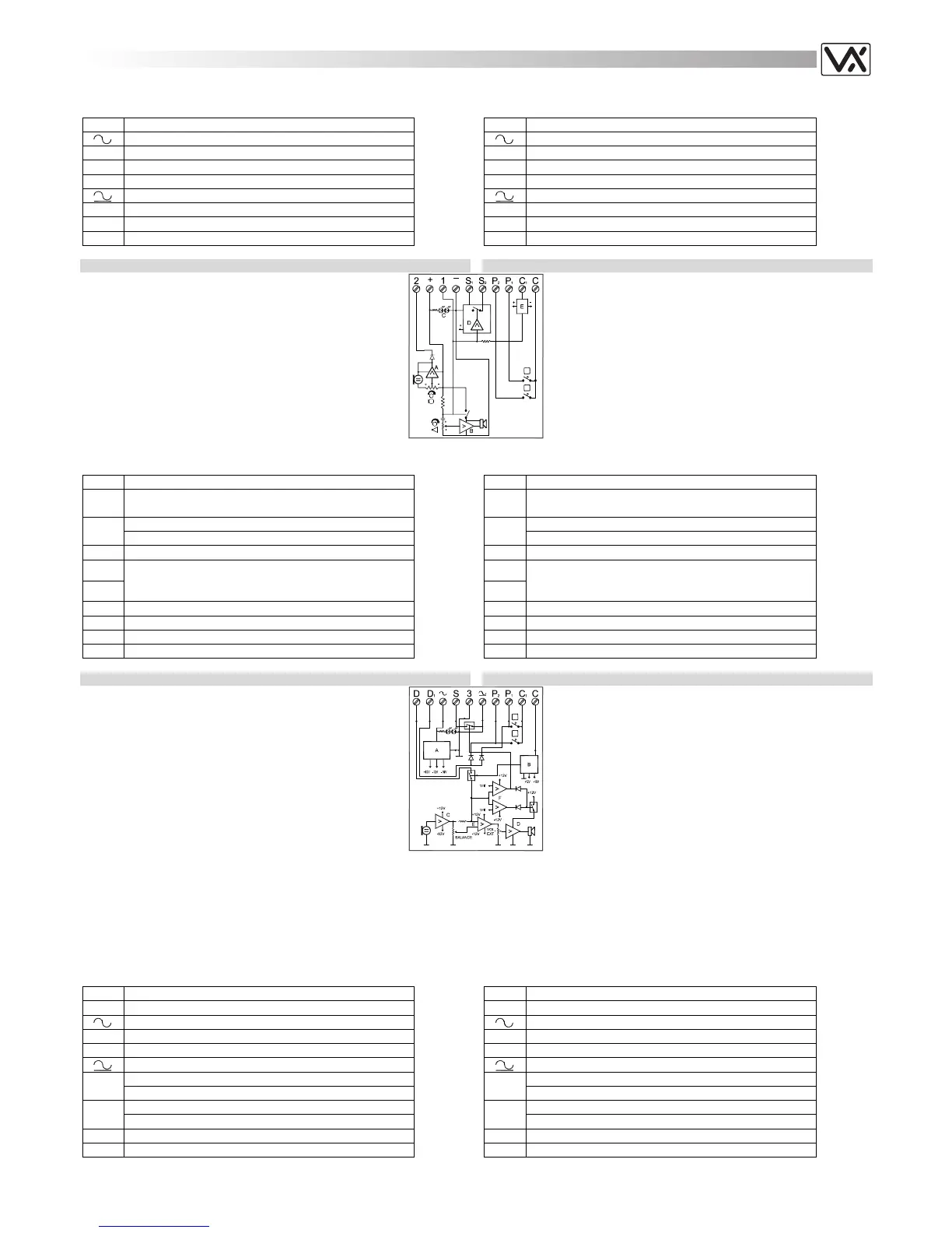
FOR “3+1” AND INTERCOMMUNICATING SYSTEMS PER SISTEMI “3+1” ED INTERCOMUNICANTI
Art.837M-0, 837M-1, 837M-2
Speaker unit for “3+1” audio door entry systems without
privacy of speech and for intercommunicating systems.
The speaker unit circuitry includes:
a. The transmitting amplifier with condenser microphone
and volume control;
b. The receiving amplifier and volume control;
c. 2 LEDs to illuminate the name plate (except the 837M-0
model).
d. The enslavement relay to enable the electric lock;
e. The modulated tone generator;
The version 837M-0 does not have the terminals “P1”,
“P2”, and “C”.
On the 837M-1, terminal “P2” is not fitted.
Art.837M-2/..
Art.837M-0, 837M-1, 837M-2
Portiere elettrico per sistemi “3+1” senza “segreto di
conversazione” e per quelli intercomunicanti.
La sua elettronica include:
a. L’amplificatore di trasmissione con microfono a
condensatore e regolazione del volume;
b. L’amplificatore di ricezione con altoparlante da 0,5W e
regolazione del volume;
c. 2 LED d’illuminazione cartellini (escluso 837M-0);
d. Il relè d’asservimento per l’attivazione della serratura
elettrica;
e. Il circuito di generazione della nota elettronica.
Nell’837M-0 non sono presenti i morsetti “P1”,”P2” e “C”,
mentre nella versione 837-1 manca solo il morsetto “P2”.
Terminals:
2
Speech output.
+
12Vdc power input for speaker unit and LEDs power
supply.
Speech input.
1
“Door Open” signal.
-
Ground.
S1
S
Normally open relay contacts (the contact between
“S” and “S1” is closed when the unit receive the
“door open” signal.
P2
Call button user Nr.2.
P1
Call button user Nr.1.
C1
Electronic call tone output (active only on call).
C
Push buttons common.
Morsettiera:
2 Uscita fonia.
+
Ingresso 12Vdc per alimentazione posto esterno e
LED.
Ingresso fonia.
1
Comando “apri-porta”.
- Massa.
S1
S
Contatti relè normalmente aperto (il contatto tra “S”
ed “S1” si chiude al ricevimento del comando “apri-
porta”).
P2 Uscita chiamata utente 2.
P1 Uscita chiamata utente 1.
C1 Uscita nota elettronica (attiva durante la chiamata).
C Comune Pulsanti.
FOR “1+1” SYSTEMS PER SISTEMI “1+1”
Art.835M-0, 835M-1, 835M-2
Speaker unit for “1+1” audio door entry systems with or
without privacy of speech.
The speaker unit circuitry includes:
a. The voltage rectifier and stabilizer circuits;
b. The modulated tone generator;
c. The transmitting amplifier with condenser microphone
and volume control;
d. The receiving amplifier and volume control;
e. The audio balance circuit with the relevant “BALANCE”
control;
f. The voltage reader circuit: depending on the voltage
changes caused by picking/hung up the handset the
Art.835M-2/..
Art.835M-0, 835M-1, 835M-2
Portiere elettrico per sistemi citofonici “1+1”.
La sua elettronica include:
a. Il circuito di rettifica e stabilizzazione della tensione;
b. Il circuito generatore della nota modulata;
c. L’amplificatore di trasmissione con microfono a
condensatore e regolazione del volume;
d. L’amplificatore di ricezione con altoparlante da 0,5W e
regolazione del volume;
e. Il circuito di bilanciamento della fonia con relativa
regolazione “BALANCE” (per eliminare l’eventuale
effetto Larsen);
f. Il circuito di lettura della tensione: in base alle variazioni
circuit enable or disable speech line and door open;
g. The enslavement relay to enable the electric lock (one contact normally
open which closes to ground on door open signal);
h. 2 LEDs to illuminate the name plate (except the 835M-0 model).
The version 835M-0 has not the terminals “P1”, “P2”, and “C1”.
On the 835M-1, terminal “P2” is not fitted.
provocate dal sollevamento o aggancio della cornetta, il circuito abilita o
disabilita la fonia e l’apertura porta.
g. il relè d’asservimento per l’attivazione della serratura elettrica (contatto
unico normalmente aperto che chiude verso massa al ricevimento del
comando “apri-porta”);
h. 2 LED di illuminazione cartellini (escluso 835M-0).
Nell’835M-0 non sono presenti i morsetti “P1”,”P2” e “C1”, mentre
nell’835M-1 manca solo il morsetto “P2”.
Terminals:
D
Common speech
D
1
Common speech diode for extension panels
Power input 13Vac
S
Output to enable the electric lock
3
Speech ground (common wire)
Power input
Call user 2, Speech user 2
P
2
Door open signal user 2
Call user 1, Speech user 1
P
1
Door open signal user 1
C
1
Common push buttons.
C
Electronic call tone output.
Morsettiera:
D Comune fonia
D
1
Comune diodi per pulsanti di chiamata aggiuntivi
Ingresso alimentazione 13Vac
S Uscita per azionamento serratura elettrica
3 Massa fonica (filo comune)
Ingresso alimentazione
Chiamata utente 2, Fonia utente 2
P
2
Comando “apri-porta” utente 2
Chiamata utente 1, Fonia utente 1
P
1
Comando “apri-porta” utente 1.
C
1
Comune pulsanti.
C Uscita nota elettronica
 Loading...