60
FIVE USERS INTERCOMMUNICATING
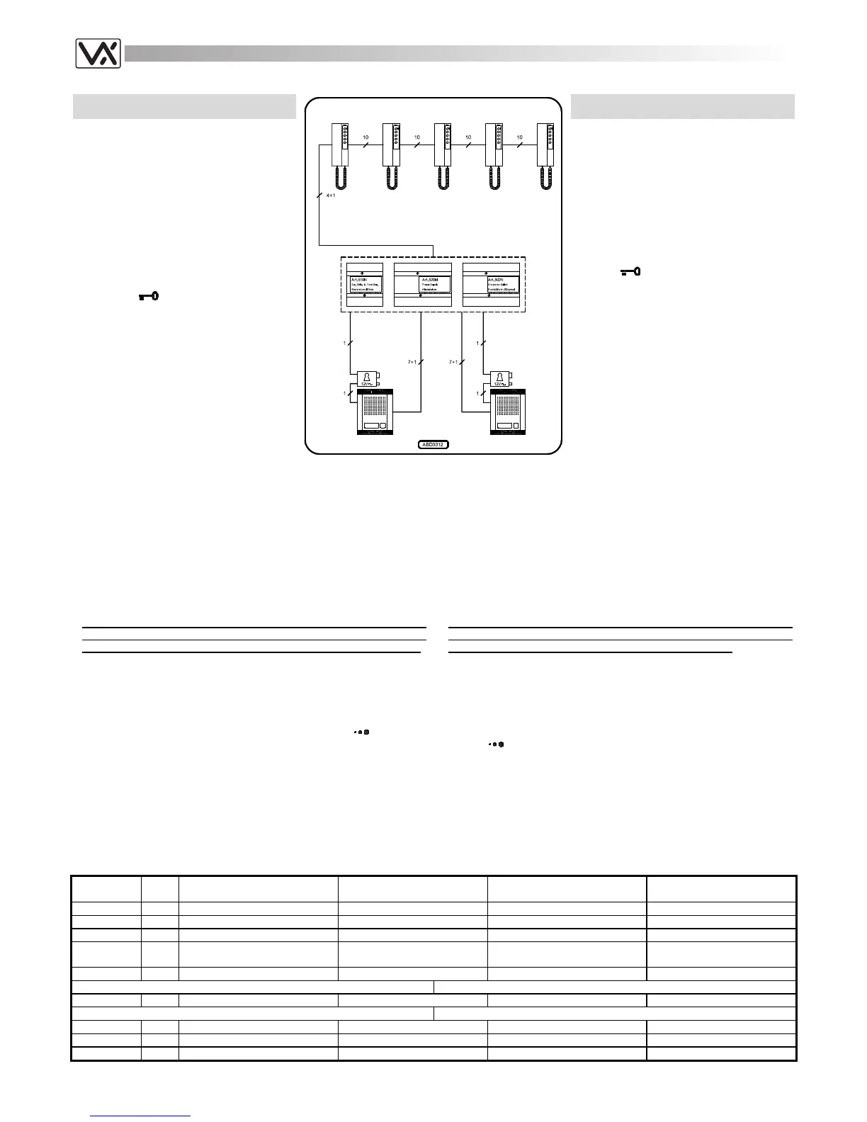
SYSTEM WITH TWO ENTRANCES
The installation shown on the diagram works
like the one on page 58 but has two
entrances.
The Art.502N (audio entrances switch)
switches the speech line and the “door open”
service on the outdoor station from which the
last call was made cutting off the second
outdoor station: so the system, on each call,
works like one with one entrance.
Like on the one entrance system but relative
to the entrance from which the last call is
made, picking up one of the handsets at any
time, it is possible to talk with the outdoor
station and to open the relevant door by
pressing the
push button.
Installing the system
a. Consult the table below to obtain the
items required.
b. Run the correct size cables (see page
25). See block diagram for number of
cores;
c. Test installation (see page 25) and in
case of any problem see the
troubleshooting guide of this manual (see
page 26).
SISTEMA INTERCOMUNICANTE A 5
UTENTI CON DUE INGRESSI
L’impianto mostrato nello schema funziona
come quello di pagina 58, ma è modificato
rispetto a quest’ultimo per avere 2 ingressi.
L’Art.502N (scambiatore d’ingressi audio)
consente di commutare la fonia ed il servizio
di “apertura-porta”, verso l’ingresso dal quale
proviene la chiamata: l’impianto, ad ogni
chiamata, lavora come se fosse ad ingresso
singolo.
Come per il sistema precedente, sollevando la
cornetta è possibile parlare con il posto
esterno ed aprire la porta premendo il
pulsante
, ma relativamente all’entrata
dalla quale è arrivata l’ultima chiamata.
Realizzazione dell’impianto
a. Consultare la tabella di fondo pagina per
il materiale occorrente;
b. Posare il cavo rispettando le sezioni dei
fili (vedi pag.25);
c. Eseguire il collaudo dell’impianto (vedi
pag.25) ed in caso di problemi consultare
la ricerca guasti del presente manuale
(vedi pag.26).
Extra services and accessories
It is possible to install on the system additional accessories or/and have
extra services by using the service push buttons (1-4) :
1. Installation of an extension sounder (see page 23 fig.4);
2. Installation of a digital codelock module (see page 38 fig.2);
3. Installation of a proximity key reader module to open the door using
proximity keys (see page 38 fig.1);
4. Enable extra services like stair lights or gate opening trough an
enslavement relay controlled by one service push button (see page
23 fig.8). Naturally the service push buttons could be used if free
(systems with less than 5 extensions).
Accessori e Servizi Ausiliari
È possibile installare nell’impianto degli accessori aggiuntivi e/o usufruire
di servizi ausiliari utilizzando uno dei pulsanti di servizio (1-4):
1. Installazione di una suoneria supplementare (vedi pag.23 fig.4);
2. Installazione di un modulo “apri-porta” a codice (vedi pag.38 fig.2);
3. Installazione di un modulo “apri-porta” con lettore di prossimità per
chiavi codificate (vedi pag.38 fig.1);
4. Attivazione di servizi ausiliari come luci scale (o apertura cancello
ecc.) tramite un relè d’asservimento comandato da un pulsante di
servizio (vedi pag.23 fig.8). Naturalmente i pulsanti di servizio
possono essere utilizzati se liberi (sistemi con meno di 5 interni).
Notes
- The call tone comes from the ear piece of the handset: to avoid
damage to the hearing, do not leave the handset close to the ear
while the relevant hook switch on the base is down for any reason;
- The jumper JP1 allows, depending on the system, to adjust the door
open signal: “T” position to have an electronic call tone, “-” position to
have a ground signal;
- As shown on the diagram, setting the jumper JP1 on “-” position and
making a link between terminals “P” and “A” for each intercom allows the
“door open” wire to be unused;
- To avoid call tone distortion, adjust the call tone volume (
) to a low or
medium level for at least 3 intercoms;
- The Art.502N (audio entrances switch) switches the speech lines and
the “door open” service to the entrance from which the call is made;
- The speech lines from the entrance switch (Art.502N) go to the
intercoms through the Art.510N which cuts off the speech lines from the
active outdoor station while an intercommunicating conversation is in
progress.
Note
- La nota elettronica è emessa dallo speaker interno alla cornetta:
per evitare danni all’udito, non tenere mai la cornetta accostata
all’orecchio se il relativo gancio sulla base è abbassato;
- Il jumper JP1 consente, in base al tipo di impianto, di adeguare il
comando “apri-porta” (morsetto “P”) del citofono: in posizione “T” è una
nota elettronica, in posizione “-“ è un segnale di massa;
- Impostando il jumper JP1 in posizione “-“ e facendo un ponte tra i
morsetti “P” ed “A” per ciascun citofono, è stato risparmiato, rispetto
all’impianto ad un ingresso, il filo per il comando “apri-porta”;
- Per evitare distorsioni della nota elettronica, è necessario impostarne il
volume (
) ad un livello medio o basso per almeno 3 citofoni.
- L’Art.502N permette di commutare l’audio ed il servizio d’apertura porta
verso il posto esterno dal quale è arrivata l’ultima chiamata;
- La linea fonica in uscita dallo scambiatore (Art.502N) passa attraverso
l’Art.510N che isola il posto esterno attivo dalla linea fonica quando è in
corso una conversazione intercomunicante.
Art.
Qty
Qta
Description Notes Descrizione Note
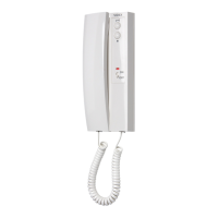
3117 5
Intercom with 5 push button
Citofono a 5 pulsanti
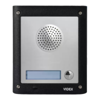
837M-1 2
Speaker unit module
Modulo portiere elettrico
520M 1
Power Supply Unit
Alimentatore
510N 1
Modulated tone generator and
speech cut off circuit
Generatore di nota elettronica e
separatore di linea fonica
502N 1
Audio Entrances Switch
Scambiatore d’Ingressi Audio
For outdoor station surface mount Per l’installazione da superficie del posto esterno
881 2
Surface mounting unit
Scatola di protezione
For outdoor station flush mount Per l’installazione da incasso del posto esterno
851 2
Front support
Supporto frontale
861 or 2
Covering frame
Cornici di protezione
871 2
Rainshield
Tettuccio antipioggia
 Loading...